


GLDM 64.1 Technical Manual rev. 1.30 February
2020
Page 30 of 50
6.10. Communication Setup Commands
– AD, CR, NA, NS, BR, DX
8.10.1. AD Device Address
– Serial channel
[ n.a. ]
This command can set up the device address in the range from 0 to 255.
Master (PC / SPS) sends
Slave (GLDM 64.1)
responds
Meaning
AD
A:000
Request: Address 0 (= factory default)
AD49
OK
Setup: Address 49
Setting the device
address to “0“ will cause the device to be permanently active, listening and responding to
every command on the bus without the need for an OP command.
Note:
After editing the address you first have to save the changes (command WP) and then restart the device.
8.10.2. NA Network Address - CANbus
[ SDO 2007 sub 02 ]
This command displays or sets a network address for the CAN interface. The permitted range is from1 to 127.
Master (PC / SPS) sends
Slave (GLDM 64.1)
responds
Meaning
NA
A:001
Show CAN interface address
NA_15
OK
Set CAN interface address to15
Factory default: 1
8.10.3. NS Network Settings
– For Serial Channel and CAN Interface
[ n.a. ]
The command
NS
<Interface> <Param> [New Value] can display or set various communication parameters in
the device.
The parameter "Interface" addresses the physical interface on the device and the parameter "Param"
addresses the available parameters for this interface. All GLDM devices have a serial channel (UART) and
a CAN interface.
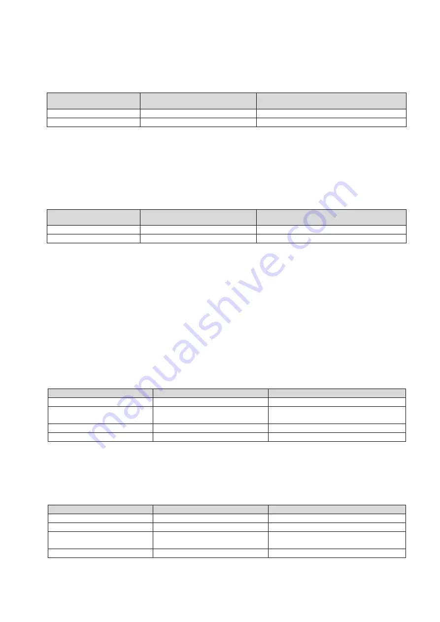
Serial channel ("Interface" = 0)
The following parameters are defined for the serial channel:
"Param"
Parameter name
Allowed values
0,
Note 1
Device ID (Read only)
N/A
1
,
Note 2
Baud rate
9600, 19200, 38400, 57600, 115200,
230400 and 460800 bit/sec.
2
,
Note 3
Loop address
0 to 255
4
,
Note 4
Tx Delay
0 to 255
Notes for the interfaces 0 (serial)
Note 1: Identical to the ID command.
Note 2: Identical to the BR command.
Note 3: Identical to the AD command. Note 4: Identical to the TD command.
CAN Interface ("Interface" = 1)
The following parameters are defined for the CAN interface:
"Param"
Parameter name
Allowed values
0,
Note 1
Device ID (Read only)
N/A
1,
Note 2
CANopen address
1 to 127
2
Bit rate
10, 20, 50, 125, 250, 500, 800 and
1000 kbit/s
6
TPDO1 Divider
0…65535
Notes for the interfaces 1 (CAN)
Note 1: Identical to the ID command.
Note 2: Identical to the NA command.