background image

h7583 tenoning Jig

-13-

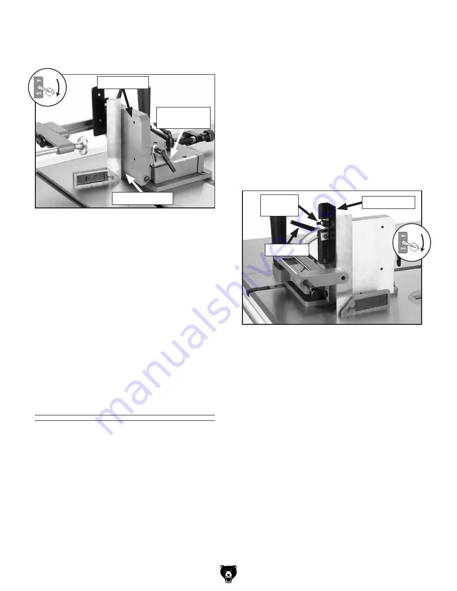
5.  thread the positive stop set screw far enough 

away from the side support so that it will not 
interfere with the next step (see 

figure 14).

6.  position  the  machinist's  square  flat  on  the 

table and up against the jig side support.

7.  loosen  the  support  lock  lever,  position  the 

side  support  flat  against  the  machinist's 
square, then, without moving the support, re-
tighten the lock lever.

8.  remove  the  square  and  re-tighten  the  stop 

set  screw  until  it  just  meets  resistance.  the 
90° positive stop is now set for quick perpen-
dicular positioning of the side support.

back Support 

adjustment

To adjust the back support:

1.  disConnECt  tABlE  sAW  FroM 

poWEr!

2.  Completely lower the saw blade so that it will 

not interfere with the measurements.

3.  Clean  away  any  debris  from  the  table  or  jig 

that  could  affect  the  measurements,  then 
insert the jig all the way into the miter slot.

4.  loosen the jam nut on the positive set screw, 

then  back  off  the  set  screw  to  allow  adjust-
ment to the back support (see 

figure 15).

figure 14. Adjusting the side support 

perpendicular to the saw table.

side support

side support 

lock lever

stop set screw

in this procedure you will adjust the back support 
perpendicular  to  the  saw  table,  then  set  the  90° 
positive stop so the back support can be returned 
to the perpendicular position after an angle cut.

5.  position  the  machinist's  square  flat  on  the 

table and up against the back support of the 
jig, as shown in 

figure 15.

6.  loosen  the  support  lock  lever,  position  the 

back  support  flat  against  the  machinist's 
square, then, without moving the support, re-
tighten the lock lever.

7.  remove  the  square  and  re-tighten  the  stop 

set screw until it just meets resistance, then 
re-tighten  the  jam  nut  to  secure  the  setting. 
the 90° positive stop is now set for quick per-
pendicular positioning of the back support.

figure 15. Adjusting the back support 

perpendicular to the saw table.

Back support

stop set 

screw

lock lever

Summary of Contents for H7583

Page 1: ...R S Manual Copyright MAY 2005 By Grizzly Industrial Inc REVISED JANUARY 2009 TS Warning No portion of this manual may be reproduced in any shape Or form without the written approval of Grizzly Industrial inc EW7181 printed IN CHINA ...

Page 2: ... personal protective equipment The manufacturer will not be held liable for injury or property damage from negligence improper training machine modifications or misuse Some dust created by power sanding sawing grinding drilling and other construction activities contains chemicals known to the State of California to cause cancer birth defects or other reproductive harm Some examples of these chemic...

Page 3: ...7 Unpacking 7 Inventory 8 Clean Up 8 Table Saw Preparation 9 Tenoning Jig Preparation 9 Assembly 9 Guide Bar Mounting Configuration 10 Guide Bar Adjustment 12 Side Support Adjustment 12 Back Support Adjustment 13 Blade Clearance Adjustment 14 SECTION 3 OPERATIONS 16 Operation Safety 16 Basic Tenon Cutting 16 SECTION 4 ACCESSORIES 22 SECTION 5 MAINTENANCE 24 Schedule 24 Cleaning 24 Lubrication Stor...

Page 4: ...he case and the difference between the manual and machine leaves you in doubt immediately call our techni cal support for updates or clarification For your convenience we always keep current Grizzly manuals and most updates available on our website at www grizzly com Any updates to your machine will be reflected in these documents as soon as they are complete Visit our site often to check for the ...

Page 5: ...andwheel H Micro Adjust Lock Lever I Slide Plate Lock Lever J Slide Plate Handle K Clamp Handle L Clamp Brace M Slide Plate N Base Plate O Guide Bar P Micro Adjust Knob L P O NOTICE If you have never used this type of machine or equipment before We strongly recommend that you read books trade magazines or get formal training before beginning any projects Regardless of the content in this section G...

Page 6: ...f dust wood metal etc can cause severe respiratory illnesses For Your Own Safety Read Instruction Manual Before Operating this Machine The purpose of safety symbols is to attract your attention to possible hazardous conditions This manual uses a series of symbols and signal words intended to convey the level of importance of the safety messages The progression of symbols is described below Remembe...

Page 7: ...ng and changing accessories 16 MAKE SURE GUARDS ARE IN PLACE AND WORK CORRECTLY BEFORE USING MACHINERY Safety Instructions for Machinery 17 REMOVE ADJUSTING KEYS AND WRENCHES Make a habit of checking for keys and adjusting wrenches before turn ing machinery ON 18 CHECK FOR DAMAGED PARTS BEFORE USING MACHINERY Check for binding or misaligned parts broken parts loose bolts and any other conditions t...

Page 8: ... into the spinning saw blade 5 SECURING WORKPIECE ALWAYS securely clamp the workpiece in the ten oning jig and make sure all fasteners and lock levers are tight before you start the saw ALWAYS make sure that the jig will not make contact with the saw blade during operation 6 JIG CONTROL ALWAYS firmly hold both tenoning jig handles when cutting NEVER hold the jig with one hand 7 ADJUSTING JIG Disco...

Page 9: ...ription Qty Square 90 1 Shop Rags Solvent As Needed Wrench 8mm 1 Wrench 10mm 1 Wrench 14mm 1 Machinist s Square 1 Needed for Setup Your machine was carefully packaged for safe transportation Remove the packaging materials from around your machine and inspect it If you discover the machine is damaged please imme diately call Customer Service at 570 546 9663 for advice Save the containers and all pa...

Page 10: ...t your local hardware store The unpainted surfaces are coated with a waxy oil to prevent corrosion during shipment Remove this protective coating with a solvent cleaner or degreaser such as shown in Figure 5 For thor ough cleaning some parts must be removed For optimum performance clean all moving parts or sliding contact surfaces Avoid chlo rine based solvents such as acetone or brake parts clean...

Page 11: ...acy of the cuts depend upon the accuracy of the saw blade Make sure that your saw blade is perpendicular to the table and parallel with the miter slots Miter Slot and Table Make sure the miter slots and table are free from burrs or debris that may interfere with the smooth operation of the jig Lighting Make sure the top of your table has adequate lighting so that the tenoning jig and workpiece are...

Page 12: ...in the outward posi tion 1 Remove the slide plate lock lever and flat washer then un thread the long set screw the lock lever was attached to see Figure 9 Note The set screw will fall down between the slide and base plates and will be acces sible in the following steps 2 Loosen the micro adjust lock lever then rotate the micro adjust knob counterclock wise to force the slide plate to move and sepa...

Page 13: ... micro adjust screw with the thread ed guide shaft of the slide plate then rotate the knob clockwise until the collar is even with the rod as shown in Figure 12 9 With one hand pressing the slide plate flat against the base plate to properly align the micro adjust assembly fully tighten the set screw on the micro adjust collar to secure it to the rod 10 Re position and secure the pointer then re i...

Page 14: ... the table saw and turn it upside down as shown in Figure 13 4 Evenly adjust the set screws shown in Figure 13 the same amount so that they protrude from the guide bar enough to take up the side to side play experienced in Step 2 5 Make sure the cap screws securing the T slot washers are tight 6 Repeat Steps 2 5 until you are satisfied with the movement of the guide bar in the saw miter slot Side ...

Page 15: ... the miter slot 4 Loosen the jam nut on the positive set screw then back off the set screw to allow adjust ment to the back support see Figure 15 Figure 14 Adjusting the side support perpendicular to the saw table Side Support Side Support Lock Lever Stop Set Screw In this procedure you will adjust the back support perpendicular to the saw table then set the 90 positive stop so the back support ca...

Page 16: ...lt At best the blade and jig will be damaged To adjust the blade clearance 1 DISCONNECT TABLE SAW FROM POWER 2 Make sure the saw blade is perpendicular to the table and parallel with the miter slot 3 Make sure the jig side support is perpen dicular to the table refer to Side Support Adjustment on Page 12 for detailed instruc tions 4 Loosen the jam nut on the safety stop set screw then back the set...

Page 17: ... side support does not quite reach the blade use a precise ruler to com pare the distance between the side support and the front and back of the blade 8 Use the micro adjust knob to align the guide bar access hole of the slide plate over the cap screw of the guide bar see Figure 17 then loosen the cap screw 9 Shift the end of the jig assembly with the access hole one way or the other so that the s...

Page 18: ...saw presents seri ous injury hazards to untrained users Read through this entire man ual and the one for your table saw to become familiar with the controls and operations before starting the table saw The following three procedures will guide you through the process of cutting a basic tenon Preparing Jig Workpiece 1 DISCONNECT TABLE SAW FROM POWER 2 Select stock for your mortise and tenon joint t...

Page 19: ...ake the mor tise generally the indents from the bit tip at the bottom of the mortise are sufficient 3 Plane a piece of wood approximately 3 8 thick to match the base plate of the jig then clamp it to the front of the table and even with the right side of the jig base plate as shown in Figure 20 Note This additional base piece provides a level surface with the jig base plate to set the workpiece on...

Page 20: ... from power and wait for the blade to come to a complete stop before removing the workpiece or moving the jig to avoid making contact with the spinning blade 4 Cut a piece of 3 4 plywood approximately 2 wide by 9 tall then mount it on the back support using either wood screws through the back of the support or recessed cap screws and hex nuts through the front see Figure 21 If your operation requi...

Page 21: ...use the micro adjust knob to cor rectly align the first structural cheek cut mark with the saw blade Note Remember to allow for the width of the kerf when aligning the workpiece Also keep the cuts close to the side support backing board as shown in Figure 24 to support the waste piece and reduce the risk of it breaking off during the cut Figure 24 Making the first cheek cut 4 Raise the saw blade t...

Page 22: ...ut 11 Turn the saw OFF disconnect it from power wait for the blade to come to a complete stop then remove the jig and additional base piece from the table 10 Position the workpiece for the third and fourth cosmetic cheek cuts as shown in Figure 26 and repeat Steps 5 8 for each cut Figure 26 Making the third and fourth cheek cuts If it is necessary to remove the side support plywood to perform a cu...

Page 23: ...st it to properly align the cut as shown in Figure 28 Note Make sure the stop block is far enough behind the blade that the workpiece will not contact it as it reaches the blade otherwise the workpiece could bind and kickback 5 Attach a backing board to the miter gauge that is aligned even with the end of the workpiece as shown in Figure 28 Note This backing board will prevent blade tear out on th...

Page 24: ...r 7 T20503 Face Shield Window T20448 Economy Clear Safety Glasses T20452 Kirova Anti Reflective Glasses T20456 Dakura Clear Safety Glasses H0736 Shop Fox Safety Glasses These glasses meet ANSI Z87 1 2003 specifica tions Buy extras for visitors or employees You can t be too careful with shop safety Figure 31 Our most popular eye protection T20448 H0736 T20452 T20502 T20503 T20456 H7237 Classic Join...

Page 25: ...s effortlessly on five ball bearing rollers attaches directly to your saw or shaper table and can be adjusted for precision results Model G4227 fits our G1023 Series except G1023SL G1023SLX G1035 G1026 and most other cabi net saws and full size shapers Model G8010 fits our G7209 G7210 14 table saws Figure 4 G4227 sliding table attachment G4227 H4332 T4 Silencer for Saw Blades Woodworkers across th...

Page 26: ...ining dust with a dry cloth If any resin has built up use a resin dissolving cleaner to remove it Treat all unpainted cast iron with a non staining rust protectant after cleaning Cleaning Lubrication Storage After thoroughly cleaning the tenoning jig use a light machine oil to lubricate all of the pivot points on the jig then wipe away the excess to avoid sawdust build up at these locations When n...

Page 27: ...S Parts Breakdown 1 2 3 4 5 6 7 8 9 10 11 12 13 14 15 16 17 18 19 20 21 22 23 24 25 26 27 28 29 30 31 32 33 34 34 1 34 2 34 3 35 36 36A 37 38 39 40 41 42 43 44 45 46 46 1 47 48 49 49 1 50 51 54 55 56 57 57 1 57 2 58 59 59 1 65 66 67 68 69 ...

Page 28: ...ECIAL SCREW M6 1 X 55 16 PH7583016 GUIDE BUSHING 47 PSS03M SET SCREW M6 1 X 8 17 PH7583017 GUIDE ROD 48 PH7583048 CLAMP SHOE 18 PSS85M SET SCREW M6 1 X 45 49 PH7583004 LOCK LEVER M6 1 X 28 19 PN01M HEX NUT M6 1 49 1 PH7583006 LOCK BUSHING 20 PH7583020 SLIDE PLATE 50 PW03M FLAT WASHER 6MM 21 PH7583021 SCALE 51 PH7583051 SIDE SUPPORT 22 PS09M PHLP HD SCR M5 8 X 10 54 PH7583054 SHOULDER SCREW M6 X 20...

Page 29: ... 0 2 Years ____ 2 8 Years ____ 8 20 Years ____20 Years 6 How many of your machines or tools are Grizzly ____ 0 2 ____ 3 5 ____ 6 9 ____10 7 Do you think your machine represents a good value _____Yes _____No 8 Would you recommend Grizzly Industrial to a friend _____Yes _____No 9 Would you allow us to use your name as a reference for Grizzly customers in your area Note We never use names more than 3...

Page 30: ...D LINE FOLD ALONG DOTTED LINE GRIZZLY INDUSTRIAL INC P O BOX 2069 BELLINGHAM WA 98227 2069 Place Stamp Here Name_______________________________ Street_______________________________ City______________State______Zip______ Send a Grizzly Catalog to a friend ...

Page 31: ...e tried in the State of Washington County of Whatcom We shall in no event be liable for death injuries to persons or property or for incidental contingent special or consequential damages arising from the use of our products To take advantage of this warranty contact us by mail or phone and give us all the details We will then issue you a Return Number which must be clearly posted on the outside a...

Page 32: ...Buy Direct and Save with Grizzly Trusted Proven and a Great Value Since 1983 ORDER 24 HOURS A DAY 1 800 523 4777 Visit Our Website Today For Current Specials ...

Reviews: