


Model G0809 (Mfd. Since 1/17)
-59-
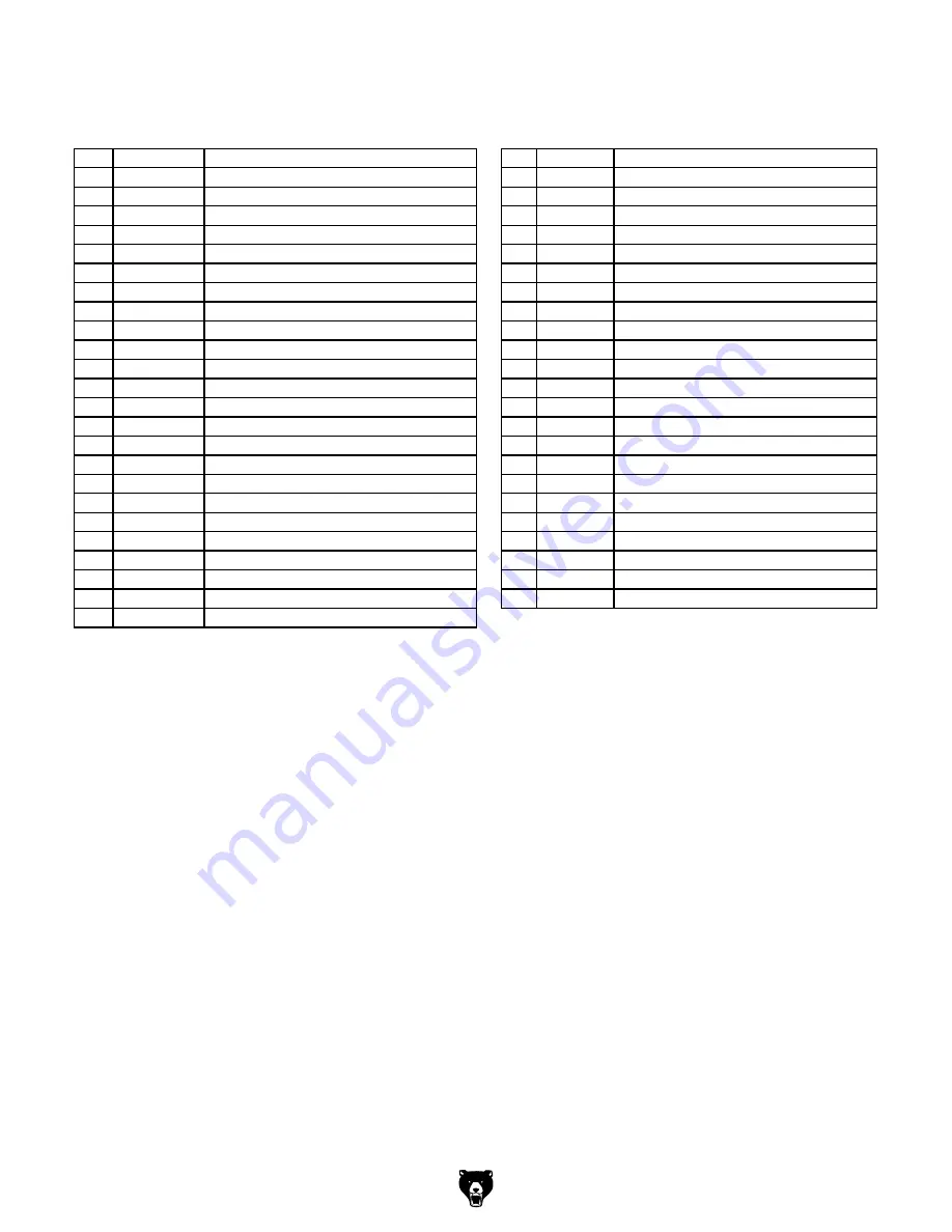
Cabinet Parts
REF PART #
DESCRIPTION
REF PART #
DESCRIPTION
1
P0809001
CAP SCREW M8-1.25 X 20
16
P0809016 CAP SCREW M6-1 X 15
2
P0809002
HEX NUT M8-1.25
17
P0809017 HEX BOLT M8-1.25 X 100
3
P0809003
FLAT WASHER 8MM
18
P0809018 LIFTING PLATE
4
P0809004
EXT RETAINING RING 15MM
19
P0809019 CASTER ASSY 37W X 75D
5
P0809005
MOTOR PLATE PIVOT BRACKET
20
P0809020 HEX NUT M6-1
6
P0809006
FLAT WASHER 8 X 20 X 2
21
P0809021 HEX NUT M8-1.25
7
P0809007
MOTOR MOUNTING PLATE
22
P0809022 HEX BOLT M8-1.25 X 25
8
P0809008
PIVOT ROD 12 X 283
23
P0809023 LOCK WASHER 8MM
9
P0809009
MOTOR 2HP 240V 1-PH
24
P0809024 KEY 6 X 6 X 40
9-1
P0809009-1
MOTOR FAN COVER
25
P0809025 SET SCREW M5-.8 X 4
9-2
P0809009-2
MOTOR FAN
26
P0809026 EXT RETAINING RING 12MM
9-3
P0809009-3
S CAPACITOR 500M 250V 2" X 4"
27
P0809027 FLAT WASHER 12MM
9-4
P0809009-4
R CAPACITOR 80M 250V 2" X 4"
28
P0809028 PEDAL
9-5
P0809009-5
MOTOR POWER CORD 14G 3W 36"
29
P0809029 DOWEL PIN 12 X 94
9-6
P0809009-6
CAPACITOR CASE
30
P0809030 LIFTING ROD
9-7
P0809009-7
CAPACITOR COVER
31
P0809031 HEX BOLT M10-1.5 X 60
9-8
P0809009-8
STRAIN RELIEF TYPE-3 M20-1.5
32
P0809032 REAR WHEEL 37W X 75D X 10B
9-9
P0809009-9
BALL BEARING 6205-2RS (FRONT)
33
P0809033 HEX NUT M10-1.5
9-10 P0809009-10 BALL BEARING 6205-2RS (REAR)
34
P0809034 ADJUSTABLE FOOT M10-1.5 X 85
10
P0809010
MOTOR PULLEY
35
P0809035 CABINET
11
P0809011
V-BELT GATES TRUFLEX 3L360
36
P0809036 SIDE COVER
12
P0809012
EXT RETAINING RING 20MM
37
P0809037 BUTTON HD CAP SCR M5-.8 X 8
13
P0809013
HEX NUT M8-1.25
38
P0809038 STRAIN RELIEF TYPE-3 M20-1.5
14
P0809014
FLAT WASHER 8MM
39
P0809039 POWER CORD 14G 3W 72" 6-15P
15
P0809015
HEX BOLT M8-1.25 X 70
Summary of Contents for G0809
Page 72: ......


