


G0803
(Mfd. Since 09/15)
-51-
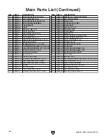
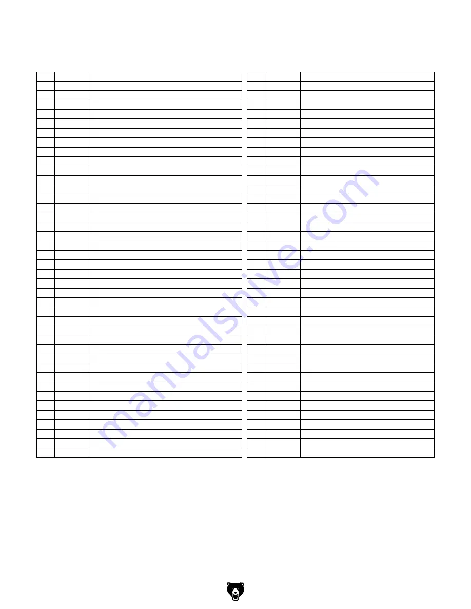
Main Parts List
REF PART #
DESCRIPTION
REF PART #
DESCRIPTION
1
P0803001 KNOB M8-1.25 X 25, DIA 50, 5-LOBE
45
P0803045 WHEEL BRUSH
2
P0803002 FLAT WASHER 8MM
46
P0803046 CARRIAGE BOLT M8-1.25 X 65
3
P0803003 COMPRESSION SPRING 2.5 X 14 X 64
47
P0803047 RUBBER FOOT
4
P0803004 CARRIAGE BOLT M8-1.25 X 80
48
P0803048 TIMING BELT 130L036
5
P0803005 WHEEL ADJUSTMENT BRACKET
49
P0803049 DUST PORT 2"
6
P0803006 CAP SCREW M5-.8 X 8
50
P0803050 PHLP HD SCR M5-.8 X 8
7
P0803007 QUICK-RELEASE PIVOT SHAFT 8 X 90
52
P0803052 DOOR LOCK CAM KNOB
8
P0803008 EXT RETAINING RING 8MM SELF-LOCKING
54
P0803054 BEARING RETAINER SCREW M5-.8 X 15
9
P0803009 HEX NUT M10-1.5
55
P0803055 BALL BEARING 606ZZ
10
P0803010 LOCK WASHER 10MM
56
P0803056 FLAT WASHER 5MM
11
P0803011 WHEEL MOUNT PLATE
57
P0803057 LOWER GUIDE ROD
12
P0803012 WHEEL SHAFT (UPPER)
58
P0803058 CAP SCREW M5-.8 X 14
13
P0803013 BALL BEARING 6000ZZ
59
P0803059 BALL BEARING 605ZZ
14
P0803014 WHEEL 9"
61
P0803061 LOWER GUIDE
15
P0803015 INT RETAINING RING 26MM
62
P0803062 SQUARE NUT M5-.8
16
P0803016 EXT RETAINING RING 10MM
63
P0803063 LOWER GUIDE BLOCK
17
P0803017 TIRE 9"
64
P0803064 CAP SCREW M5-.8 X 12
18
P0803018 WHEEL COVER (UPPER)
65
P0803065 FLAT WASHER 6MM
19
P0803019 BLADE 62" X 3/8" X 0.025" 10 TPI RAKER
66
P0803066 CAP SCREW M6-1 X 10
20
P0803020 WHEEL COVER (LOWER)
67
P0803067 LOWER BLADE COVER
21
P0803021 LOCK NUT M6-1
68
P0803068 FLAT WASHER 4MM
22
P0803022 BUSHING
69
P0803069 PHLP HD SCR M4-.7 X 10
23
P0803023 CAP SCREW M6-1 X 16
70
P0803070 STRAIN RELIEF M16-2 TYPE-3
25
P0803025 TAP SCREW M5 X 14
71
P0803071 GUIDE PLATE
26
P0803026 WHEEL PULLEY
72
P0803072 SET SCREW M4-.7 X 6
27
P0803027 WHEEL SHAFT (LOWER)
73
P0803073 PINION
28
P0803028 HEX NUT M6-1
74
P0803074 ADJUSTMENT KNOB SEAT
29
P0803029 HEX BOLT M6-1 X 16
76
P0803076 CAP SCREW M5-.8 X 10
30
P0803030 LOCK NUT M12-1.75
77
P0803077 KNOB W/SHAFT 6 X 22, DIA 32, 6-LOBE
31
P0803031 LIFTING HANDLE
78
P0803078 UPPER GUIDE
32
P0803032 PHLP HD SCR M6-1 X 10
79
P0803079 UPPER GUIDE ROD
33
P0803033 FRAME
82
P0803082 CAP SCREW M5-.8 X 16
34
P0803034 WIRE CONNECTOR
85
P0803085 UPPER BLADE COVER ASSEMBLY
35
P0803035 SWITCH MOUNTING PLATE
86
P0803086 SQUARE NUT M8-1.25
36
P0803036 PHLP HD SCR M5-.8 X 10
87
P0803087 UPPER GUIDE BLOCK
37
P0803037 PADDLE SWITCH W/KEY GRIZZLY G8988
91
P0803091 KNOB BOLT M8-1.25 X 14, DIA 32, 6-LOBE
38
P0803038 ROCKER SWITCH GORBO XCK-017 10(4) A
93
P0803093 COMPRESSION SPRING 1 X 13 X 18
39
P0803039 LOCK WASHER 5MM
94
P0803094 KNOB BOLT M8-1.25 X 35, DIA 32, 6-LOBE
40
P0803040 EXT TOOTH WASHER 5MM
96
P0803096 RELEASE WHEEL
42
P0803042 HEX NUT M8-1.25
99
P0803099 QUICK-RELEASE MOUNT BRACKET
44
P0803044 SPACER
100 P0803100 WAVY WASHER 19MM
Summary of Contents for G0803
Page 56: ...54 G0803 Mfd Since 09 15...
Page 60: ......