Grizzly G0803 Owner'S Manual Download Page 12

-10-

G0803


(Mfd. Since 09/15)

Additional Safety for Bandsaws

Serious cuts, amputation, or death can occur from contact with the moving saw blade during 

operation or if blade breakage occurs. To reduce this risk, anyone operating this machine MUST 

completely heed the hazards and warnings below.

BLADE CONTROL. To avoid risk of injury due to 
blade  contact,  always  allow  blade  to  stop  on  its 
own. DO NOT try to stop or slow blade with your 
hand or the workpiece. 

GUARDS/COVERS.  The  blade  guard  protects 
operator from moving bandsaw blade. The wheel 
covers  protect  operator  from  getting  entangled 
with rotating wheels. ONLY operate this bandsaw 
with  blade  guard  in  proper  position  and  wheel 
covers completely closed.

BLADE REPLACEMENT. To avoid mishaps that 
could  result  in  operator  injury,  make  sure  blade 
teeth face down toward table and blade is prop-
erly tensioned and tracked before operating.

UPPER BLADE GUIDE SUPPORT. To  reduce 
exposure of operator to blade and provide maxi-
mum  blade  support  while  cutting,  keep  upper 
blade guides adjusted to not more than 1" above 
workpiece.

CUTTING TECHNIQUES. To avoid blade getting 
pulled  off  wheels  or  accidentally  breaking  and 
striking  operator,  always  turn  bandsaw 

OFF  and 

wait for blade to come to a complete stop before 
backing  workpiece  out  of  blade.  DO  NOT  back 
workpiece away from blade while bandsaw is run-
ning. 

WORKPIECE SUPPORT. To maintain maximum 
control  and  reduce  risk  of  blade  contact/break-
age,  always  ensure  adequate  support  of  long/
large workpieces. Always keep workpiece flat and 
firm against table/fence when cutting to avoid loss 
of  control.  If  necessary,  use  a  jig  or  other  work-
holding device. 

HAND PLACEMENT.  Placing  hands  or  fingers 
in  line  with  blade  during  operation  may  result  in 
serious injury. Do not position fingers or hands in 
line with blade, and never reach under table while 
blade  is  moving.  During  operation  use  brush  or 
push stick, not hands, to clean chips/cutoff scraps 
from table.

SMALL/NARROW WORKPIECES. Cutting small/
narrow workpieces increases the risk of acciden-
tal  blade  contact.  Always  support/feed  small  or 
narrow workpieces with push sticks, push blocks, 
jig, vise, or some type of clamping fixture.

BLADE SPEED. Cutting workpiece before blade 
is  at  full  speed  could  cause  blade  to  grab  work-
piece and pull operator’s hands into blade. Allow 
blade to reach full speed before starting cut. DO 
NOT  start  machine  with  workpiece  contacting 
blade. 

BLADE CONDITION.  Dull  blades  require  more 
effort to perform cut, increasing risk of accidents. 
Do  not  operate  with  dirty,  dull,  cracked  or  badly 
worn  blade.  Inspect  blades  for  cracks  and  miss-
ing teeth before each use. Always maintain proper 
blade tension.

FEED RATE. To avoid risk of workpiece slipping 
and  causing  operator  injury,  always  feed  stock 
evenly  and  smoothly.  DO  NOT  force  or  twist 
blade while cutting, especially when sawing small 
curves.  This  could  result  in  blade  damage  or 
breakage.

CLEARING JAMS.  Always  stop  bandsaw  and 
disconnect  power  before  clearing  scrap  pieces 
that get stuck between blade and table insert.

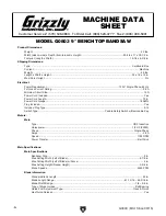
Summary of Contents for G0803

Page 1: ...For models manufactured since 09 15 COPYRIGHT OCTOBER 2015 BY GRIZZLY INDUSTRIAL INC WARNING NO PORTION OF THIS MANUAL MAY BE REPRODUCED IN ANY SHAPE OR FORM WITHOUT THE WRITTEN APPROVAL OF GRIZZLY IN...

Page 2: ...g grinding tool integrity and the usage of personal protective equipment The manufacturer will not be held liable for injury or property damage from negligence improper training machine modifications...

Page 3: ...Blade Guide Bearings 23 Calibrating Miter Slot with Blade 24 Calibrating Fence with Miter Slot 25 SECTION 4 OPERATIONS 26 Operation Overview 26 Disabling Switch 27 Workpiece Inspection 28 Setting Upp...

Page 4: ...hine We made every effort to be exact with the instruc tions specifications drawings and photographs in this manual Sometimes we make mistakes but our policy of continuous improvement also means that...

Page 5: ...N M O Q P S R T U V W J K G A Upper Wheel Cover B Blade Tension Knob C Guide Post D Upper Blade Guide Bearings E Fence F Miter Gauge G Fence Rail H Fence Lock Handle I Lower Wheel Cover J ON OFF Swit...

Page 6: ...ntire manual BEFORE using machine Guide Post Figure 2 Guide post controls E F Fence and Miter Gauge E Guide Post Adjustment Knob Rotate to adjust height of blade guides above workpiece F Guide Post Lo...

Page 7: ...erclockwise as viewed from rear of machine to quickly release blade tension Move clockwise to re tension blade I Tracking Knob Rotate to adjust blade track ing refer to Page 17 for more information J...

Page 8: ...35 x 18 x 13 in Must Ship Upright No Electrical Power Requirement 120V Single Phase 60 Hz Full Load Current Rating 2 8A Minimum Circuit Size 15A Power Cord Included Yes Power Cord Length 72 in Power...

Page 9: ...um Fence Extruded Aluminum Base Stand Pre Formed Steel Frame Body Pre Formed Steel Wheels Balanced Aluminum Tire Rubber Wheel Cover Steel Paint Type Finish Urethane Other Related Information Wheel Dia...

Page 10: ...DANGEROUS ENVIRONMENTS Do not use machinery in areas that are wet cluttered or have poor lighting Operating machinery in these areas greatly increases the risk of accidents and injury MENTAL ALERTNESS...

Page 11: ...ing parts or flying debris Make sure they are properly installed undamaged and working correctly BEFORE operating machine FORCING MACHINERY Do not force machine It will do the job safer and better at...

Page 12: ...f blade contact break age always ensure adequate support of long large workpieces Always keep workpiece flat and firm against table fence when cutting to avoid loss of control If necessary use a jig o...

Page 13: ...ed circuit To reduce the risk of these hazards avoid over loading the machine during operation and make sure it is connected to a power supply circuit that meets the specified circuit requirements For...

Page 14: ...size gets longer and the gauge size gets smaller higher gauge numbers indicate smaller sizes Any extension cord used with this machine must be in good condition and contain a ground wire and matching...

Page 15: ...hen you are completely satisfied with the condi tion of your shipment inventory the contents Unpacking SUFFOCATION HAZARD Keep children and pets away from plastic bags or packing materials shipped wit...

Page 16: ...Below is the minimum amount of space needed for the machine Placement Location Bench Mounting Figure 9 Direct Mount setup Machine Base Workbench Lag Screw Flat Washer Another option is a Direct Mount...

Page 17: ...nd lock lever Do not fully tighten yet 4 Completely raise upper blade guide assem bly then place a 90 square flat on table against side of blade 5 Use adjustment knob to tilt table until square is fla...

Page 18: ...fore performing other necessary adjustments Below is an overview of all the adjustments and the order in which they should be performed 1 Blade Tracking 2 Dust Collection 3 Test Run 4 Tension Blade 5...

Page 19: ...e how the blade tracks Bandsaw wheels are either flat or crowned and both shapes track differently The G0803 has crowned wheels As the wheels spin a properly tracking blade naturally tracks at the cen...

Page 20: ...NECT MACHINE FROM POWER 2 Adjust upper and lower blade guides away from blade and raise upper guides all the way up refer to Adjusting Blade Guide Bearings on Page 23 for detailed instruc tions Note W...

Page 21: ...dust with a dust collection system Test Run Once assembly is complete test run the machine to ensure it is properly connected to power and safety components are functioning correctly If you find an u...

Page 22: ...lection Optimal cutting results for any type of workpiece are achieved through a combination of correct blade selection proper blade tension properly adjusted blade guides and other bandsaw compo nent...

Page 23: ...entally and repeat Step 6 until properly tensioned 6 Adjust blade guides as described in Adjusting Blade Support Bearings and Adjusting Blade Guide Bearings on Pages 22 23 Using the flutter method you...

Page 24: ...o the upper support bearings To access the lower support bearing you must open the lower wheel cover see Page 3 for reference Important To ensure best results while cutting make sure the blade is trac...

Page 25: ...ade gullets Note With wider blades it may not be possi ble to bring the guide bearings just behind the blade gullets Position them as far forward as possible without allowing the guide bearing housing...

Page 26: ...alibrating Miter Slot with Blade To ensure cutting accuracy the table must be carefully positioned so the miter slot is parallel with the bandsaw blade Before beginning this procedure make sure blade...

Page 27: ...ange bolts Cap Screws 3 of 4 To ensure accurate cutting when using the fence the face of the fence must be parallel to the table miter slot and thus to the side of the blade Before beginning this proc...

Page 28: ...ers away from the blade and uses a push stick to feed narrow workpieces 9 Stops the bandsaw The purpose of this overview is to provide the nov ice machine operator with a basic understanding of how th...

Page 29: ...blade when cutting around tight corners Allow the blade to saw its way around the corners Always use relief cuts when possible Misusing the saw or using incorrect tech niques e g twisting the blade wi...

Page 30: ...s that do not have large loose knots or plan ahead to avoid cutting through them Wet or Green Stock Cutting wood with a moisture content over 20 causes unneces sary wear on the blades increases the ri...

Page 31: ...t as well as how accurately it can cut a straight line Always pick the size of blade that best suits your application Curve Cutting Use the chart in Figure 35 to determine the correct blade for curve...

Page 32: ...ne pitch will cut slower but smoother while fewer teeth per inch coarse pitch will cut rougher but faster As a general rule choose blades that will have at least three teeth in the material at all tim...

Page 33: ...ZARD Bandsaw blades are sharp and difficult to handle Wear heavy leather gloves while handling to reduce the risk of being cut Figure 37 Removing blade 8 Position new blade so teeth are facing you and...

Page 34: ...k when ripping narrow pieces Failure to follow these warnings may result in amputation or laceration injuries Crosscutting is the process of cutting across the grain of wood For plywood and other proc...

Page 35: ...fer larg er gullet capacities for clearing sawdust which reduces heat buildup and strain on the motor Cutting Curves When cutting curves simultaneously feed and turn the stock carefully so the blade f...

Page 36: ...that will not interfere with cutting Hot glue on the edges works well as do brad nails through the waste portion Be careful not to cut into the brads or you may break the blade 3 Lay out the shape you...

Page 37: ...rformance HP and Raker RK blades are specifically designed for detail work in 1 and smaller kiln dried wood when a very clean finish is required They are also effec tive in plywood and other woods whe...

Page 38: ...y Glasses T20452 Kirova Anti Reflective S Glasses H7194 Bifocal Safety Glasses 1 5 H7195 Bifocal Safety Glasses 2 0 H7196 Bifocal Safety Glasses 2 5 T20502 T20452 T20503 H7194 T20451 D3197 24 Aluminum...

Page 39: ...d legs and adjustable rubber feet ensure stability and reduce machine vibration Butcher block finish table top measures 1 x 13 x 23 and is 30 1 2 from the floor Bottom measures 21 x 32 700 lb Capacity...

Page 40: ...e rubber tires on the wheels Clean vacuum dust buildup from inside cabi net and off motor Schedule As the bandsaw ages the rubber tires on the wheels may need to be redressed if they harden or glaze o...

Page 41: ...de for task 5 Workpiece crooked fence loose or misadjusted 6 Blade slipping on wheels 7 Belt slipping 8 Motor overheated 9 Run capacitor at fault 10 Pulley sprocket slipping on shaft 1 Only cut wood e...

Page 42: ...uide bracket 4 Adjust blade guides as close to workpiece as possible Pages 22 23 5 Check blade installation make sure teeth face front of machine and point down in table throat Re install blade if nec...

Page 43: ...nting bolts or tilt lock lever 8 Align table and fence with blade Page 24 9 Adjust blade guide bearings and support bearing for correct blade support Pages 22 23 10 Replace blade Page 31 11 Use a blad...

Page 44: ...lection Deflection is checked by push ing belt with moderate pressure as shown in Figure 50 and noting how much it moves If the belt is not properly tensioned per form the Tensioning Belt procedure Pu...

Page 45: ...lt from motor pulley To ensure optimum power transmission from the motor to the blade the belt must be in good condi tion and be properly tensioned Replace the belt if it shows signs of cracking fray...

Page 46: ...SCONNECT MACHINE FROM POWER 2 Remove table 3 With blade on and properly tensioned hold a straightedge close to center of both wheels Make sure straightedge fully extends across the rims of both wheels...

Page 47: ...3 onto wheel shaft 6 Re install wheel and secure it in place 7 Re install blade and properly tension it Figure 55 Example of measuring the distance to shim the wheel to be coplanar 3 With straightedge...

Page 48: ...loosened in Step 6 3 Use a straightedge to check wheels at A and B locations see Figure 57 The wheels should align If the wheels do not align they require lat eral adjustment see Figure 58 proceed to...

Page 49: ...ely touches one end of board Blade Lead Bandsaw blades may wander off the cut line when sawing as shown in Figure 59 This is called blade lead Blade lead is usually caused by too fast of a feed rate a...

Page 50: ...t the time of printing but may not match your machine If you find this to be the case use the wiring diagram inside the motor junction box CAPACITORS INVERTERS Some capacitors and power inverters stor...

Page 51: ...round Ground Hot Neutral Ground LED Driver LED 5V700 Hopestar 120V 5 5W E337681 Gorbo XCK 017 10 4 A 250V 6A ON OFF Switch KEDU HY18 250V 12A Lamp Switch Run Capacitor CBB60 30uF 250VAC Wiring Diagram...

Page 52: ...22 23 14 25 26 27 28 29 30 31 32 33 34 35 36 37 38 39 40 36 42 2 2 44 45 46 48 47 49 21 52 23 54 54 55 55 56 50 56 57 58 58 59 59 56 56 61 62 62 63 64 65 66 67 68 69 70 71 72 73 74 65 76 77 78 79 56 6...

Page 53: ...3 8 X 0 025 10 TPI RAKER 66 P0803066 CAP SCREW M6 1 X 10 20 P0803020 WHEEL COVER LOWER 67 P0803067 LOWER BLADE COVER 21 P0803021 LOCK NUT M6 1 68 P0803068 FLAT WASHER 4MM 22 P0803022 BUSHING 69 P08030...

Page 54: ...6 116 P0803116 BEVEL INDICATOR 145 P0803145 SPRING PLATE 119 P0803119 GEARED KNOB 12T 12L X 40D 147 P0803147 GUIDE RAIL CAP LEFT 120 P0803120 COMPRESSION SPRING 0 7 X 9 8 X 25 148 P0803148 GUIDE RAIL...

Page 55: ...ess otherwise noted Labels MUST be made of chemical resistant material COPYRIGHT GRIZZLY INDUSTRIAL INC OR GRIZZLY MACHINES ONLY DO NOT REPRODUCE OR CHANGE THIS ARTWORK THOUT WRITTEN APPROVAL Grizzly...

Page 56: ...54 G0803 Mfd Since 09 15...

Page 57: ...metalworker ____ 0 2 Years ____ 2 8 Years ____ 8 20 Years ____20 Years 6 How many of your machines or tools are Grizzly ____ 0 2 ____ 3 5 ____ 6 9 ____10 7 Do you think your machine represents a good...

Page 58: ...LINE FOLD ALONG DOTTED LINE GRIZZLY INDUSTRIAL INC P O BOX 2069 BELLINGHAM WA 98227 2069 Place Stamp Here Name_______________________________ Street_______________________________ City______________S...

Page 59: ...tried in the State of Washington County of Whatcom We shall in no event be liable for death injuries to persons or property or for incidental contingent special or consequential damages arising from...

Page 60: ......

Reviews: