Grizzly G0725 Owner'S Manual Download Page 31

Model G0725 (Mfd. Since 02/20)

-29-

SECTION 5: ACCESSORIES

D1123—Jointer/Planer Knife Hone
Add a razor hone to your planer and jointer knives 
with this hand-held sharpening device. The handy 
tool  sharpens  flat  and  beveled  surfaces  quickly 
and easily. Great for touch-ups.

Figure 39. D1123 Jointer/Planer Knife Hone.

Installing unapproved accessories may 

cause machine to malfunction, resulting in 

serious personal injury or machine damage. 

To reduce this risk, only install accessories 

recommended for this machine by Grizzly. 

NOTICE

Refer to our website or latest catalog for 

additional recommended accessories.

order online at


www.grizzly.com


or call


1-800-523-4777

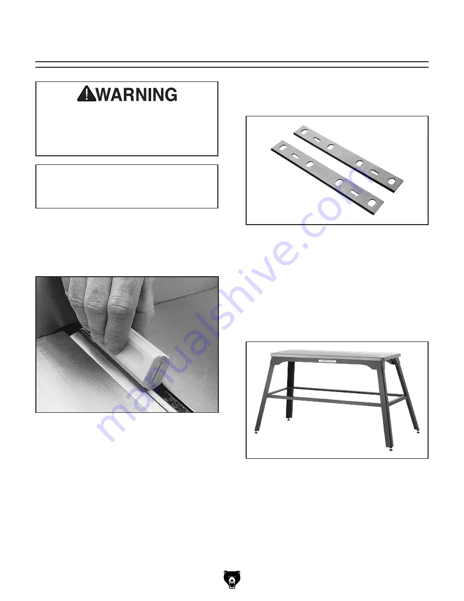
Figure 40. H9837 Replacement Knives.

H9837—6" Jointer Knives (Set of 2)
Replacement  jointer  knives  made  specifically  for 
the G0725 Jointer.

D3640—Shop Fox Tool Table Plus
The  Tool  Table  Plus  was  designed  in  response 
to  customer  requests  for  a  slightly  wider  and 
taller table to accommodate small planers, wood 
lathes,  sanders  and  a  variety  of  other  benchtop 
machines. The butcher block finish table is 1-1/4" 
thick and measures 14" x 40". The total height of 
the  tool  table  is  33".  When  assembled  properly, 
the tool table has a 700 lb. maximum capacity.

Figure 41. D3640 Shop Fox Tool Table Plus.

Summary of Contents for G0725

Page 1: ...red since 02 20 COPYRIGHT SEPTEMBER 2011 BY GRIZZLY INDUSTRIAL INC REVISED MAY 2020 MN WARNING NO PORTION OF THIS MANUAL MAY BE REPRODUCED IN ANY SHAPE OR FORM WITHOUT THE WRITTEN APPROVAL OF GRIZZLY...

Page 2: ...g grinding tool integrity and the usage of personal protective equipment The manufacturer will not be held liable for injury or property damage from negligence improper training machine modifications...

Page 3: ...17 Dust Collection 18 Test Run 19 SECTION 4 OPERATIONS 20 Operation Overview 20 Stock Inspection Requirements 21 Squaring Stock 22 Setting Fence Stops 23 Setting Depth of Cut 25 Surface Planing 26 Edg...

Page 4: ...cumentation Manager P O Box 2069 Bellingham WA 98227 2069 Email manuals grizzly com Contact Info We are proud to provide a high quality owner s manual with your new machine We made every effort to be...

Page 5: ...ure 1 G0725 identification front For Your Own Safety Read Instruction Manual Before Operating Jointer a Wear eye protection b Always keep cutterhead and drive guards in place and proper operating cond...

Page 6: ...ter mines the depth of the cut E Depth of Cut Adjustment Knob This knob adjusts height of infeed table controlling depth of cut Best results are achieved by lim iting maximum depth to 1 8 when edge jo...

Page 7: ...15 x 11 in Electrical Power Requirement 110V Single Phase 60 Hz Full Load Current Rating 12A Minimum Circuit Size 15A Connection Type Cord Plug Power Cord Included Yes Power Cord Length 8 ft Power Cor...

Page 8: ...s 3 32 in Knife Adjustment Jack Screws Table Information Table Length 28 1 2 in Table Width 6 1 4 in Table Thickness 1 4 in Table Adjustment Type Knob Table Movement Type Swing Construction Body Assem...

Page 9: ...proof DANGEROUS ENVIRONMENTS Do not use machinery in areas that are wet cluttered or have poor lighting Operating machinery in these areas greatly increases the risk of accidents and injury MENTAL AL...

Page 10: ...moving parts or flying debris Make sure they are properly installed undamaged and working correctly BEFORE operating machine FORCING MACHINERY Do not force machine It will do the job safer and better...

Page 11: ...res more cutting force which produces chat ter or excessive chip out Always joint or surface plane WITH the grain CUTTING LIMITATIONS Cutting workpieces that do not meet minimum dimension requirements...

Page 12: ...sized circuit To reduce the risk of these hazards avoid over loading the machine during operation and make sure it is connected to a power supply circuit that meets the specified circuit requirements...

Page 13: ...rd size gets longer and the gauge size gets smaller higher gauge numbers indicate smaller sizes Any extension cord used with this machine must be in good condition and contain a ground wire and matchi...

Page 14: ...achine Wear safety glasses during the entire setup process Needed for Setup The following items are needed but not included for the setup assembly of this machine This machine was carefully packaged f...

Page 15: ...ms get lost in packaging materials while unpack ing or they are pre installed at the factory Jointer Inventory Figures 6 7 Qty A Jointer Bed Assembly 1 B Fence 1 C Dust Collection Bag 1 D Limit Block...

Page 16: ...machine The time you spend doing this now will give you a better appreciation for the proper care of your machine s unpainted surfaces There are many ways to remove this rust preven tative but the fol...

Page 17: ...with lag screws and washers Mounting Figure 9 Example of a Through Mount setup Figure 10 Example of a Direct Mount setup To assemble jointer 1 Use 2 M8 1 25 x 20 cap screws and 2 8mm lock washers to a...

Page 18: ...fence to fence bracket assembly Cap Screws Limit Plate Tab Limit Block Bracket Assembly Fence Plate x 2 6 Slide the fence bracket assembly onto the support dovetails as shown in Figure 15 8 Slide the...

Page 19: ...e 18 If your cutterhead knives brush the straight edge and move it slightly 1 8 forward and back when you turn the cutterhead then no adjustments are necessary If the knives fall below the straightedg...

Page 20: ...tall dust collection chute and bag 1 Install the dust chute by attaching the dust chute to the chip exhaust and tighten the hex nut 2 Slip the bag clamp over the collection bag then attach the collect...

Page 21: ...ower and safety components are functioning correctly If you find an unusual problem during the test run immediately stop the machine disconnect it from power and fix the problem BEFORE operating the m...

Page 22: ...duce risk of eye injury from flying chips or lung damage from breathing dust always wear safety glasses and a respirator when operating this machine If you are not experienced with this type of machin...

Page 23: ...objects from the work piece Make sure that any stock you pro cess with the jointer is clean and free of dirt nails staples tiny rocks or any other foreign objects that could damage the cutterhead The...

Page 24: ...y Jointed Edge 4 Rip Cut on a Table Saw Jointed edge of workpiece is placed against a table saw fence and opposite edge cut off Squaring stock means making it flat and paral lel along both length and...

Page 25: ...when it contacts limit block shaft 90 stop is not adjusted correctly Proceed to Steps 4 6 4 Bring fence to 90 then loosen jam nut locat ed on rear of limit block shaft see Figure 28 Note Keep limit pl...

Page 26: ...h setting frequently with a machinist s combination square and re adjust as necessary Figure 29 Checking 45 fence stop 45 Square Figure 30 Adjusting the inward stop Limit Plate Inward Stop Bolt Limit...

Page 27: ...m 1 Figure 34 Zero stop components Jam Nut Zero Stop Set Screw Infeed Table Adjustment Knob To set zero stop 1 Place a straightedge on top of outfeed table see Figure 35 and use infeed table adjust me...

Page 28: ...nce to 90 4 Start jointer 5 Place workpiece firmly against fence and infeed table CAUTION To ensure workpiece remains stable during cut concave sides of workpiece must face toward table and fence 7 Re...

Page 29: ...workpiece remains stable during cut concave sides of workpiece must face toward table and fence 6 Feed workpiece completely across cutter head while keeping it firmly against fence and tables during...

Page 30: ...end of the workpiece while feeding and repeat same action with your trailing hand when it gets within 4 of cutterhead To help keep your hands safe DO NOT let them get closer than 4 from moving cutterh...

Page 31: ...TICE Refer to our website or latest catalog for additional recommended accessories order online at www grizzly com or call 1 800 523 4777 Figure 40 H9837 Replacement Knives H9837 6 Jointer Knives Set...

Page 32: ...in a low risk of injury and proper machine operation if you ever observe any of the items below shut down the machine immediately and fix the problem before continuing operations Loose mounting bolts...

Page 33: ...with correct moisture content without glues and little pitch resins Page 21 2 Re tension or replace cutterhead belt Page 33 3 Test for good contacts correct the wiring Page 36 4 Remove replace brushes...

Page 34: ...the nicked knives sideways sharpen or replace blade Page 35 Uneven cutter marks wavy surface or chatter marks across the face of the board 1 Feeding workpiece too fast 2 Knives not adjusted evenly wit...

Page 35: ...the belt with moderate pressure from your thumb or forefinger The belt is properly aligned if it lies flat and straight on the motor shaft and drive pulley Belt damage will be evident on inspection 6...

Page 36: ...me to unscrew the brush caps see Figure 44 Note When you remove the brush caps a spring will pop out of the socket the carbon brush is firmly attached to this spring When you buy a new brush kit you w...

Page 37: ...t be parallel If the knife is not parallel to the outfeed table use the knife adjustment jack screws see Figure 47 to fine tune the position of the knife Refer to Checking Outfeed Table Alignment on P...

Page 38: ...t at the time of printing but may not match your machine If you find this to be the case use the wiring diagram inside the motor junction box CAPACITORS INVERTERS Some capacitors and power inverters s...

Page 39: ...Model G0725 Mfd Since 02 20 37 READ ELECTRICAL SAFETY ON PAGE 36 Wiring Diagram PADDLE SWITCH viewed from behind Ground Ground Motor 1 5 HP 110V Neutral Hot Ground 110 VAC 5 15 Plug...

Page 40: ...87 89 93 81 92 94 95 96 97 98 99 100 104 105 106 107 108 109 110 111 112 113 63 14 5 16 72 71 15 49 2AV2 2V2 3V2 7V2 8V2 9V2 10 11 12 13 55 62 63V2 64 65 66 65 66 67 68 68 73 4 5 6 71V2 76 83 57V2 23...

Page 41: ...71V2 T NUT M8 1 25 V2 08 18 24 P0725024 MOTOR 2HP UNIVERSAL 72 P0725072 HEX BOLT M8 1 25 X 35 24 1 P0725024 1 CARBON BRUSH SET 73 P0725073 SHAFT RETAINER M10 24 2 P0725024 2 BRUSH COVER 74 P0725074 E...

Page 42: ...ded Mfd for Grizzly in Taiwan Date SN Motor 1 1 2 HP 110V 1 Ph 60 Hz Full Load Amp Draw 12A Cutterhead 2 Knife 1 7 8 Dia Replacement Knives H9837 Knife Size 6 1 2 x 7 8 x 3 32 Maximum Depth of Cut 1 8...

Page 43: ...ontingent special or consequential damages arising from the use of our products The manufacturers reserve the right to change specifications at any time because they constantly strive to achieve bette...

Page 44: ......

Reviews: