58
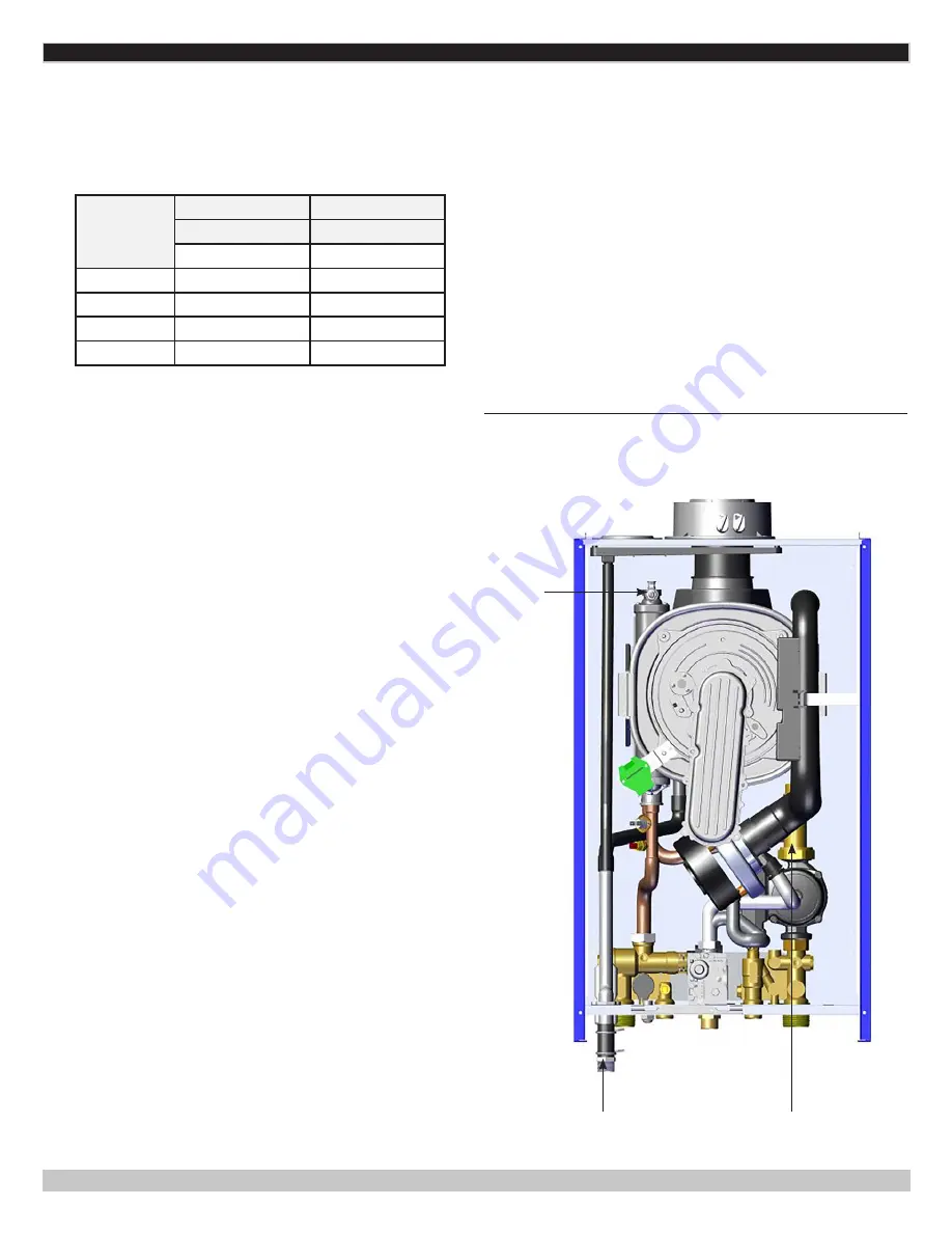
FIGURE 9-1 CONDENSATE DRAIN , AIR VENT AND
AERATOR
MODEL GMCB200 SHOWN (LOCATION SIMILAR IN
ALL SIZES)
9 - START UP PROCEDURE
Condensate Drain
• It is manufacturer recommended that when replacing a
cast iron boiler the system be flushed until the water is
clean.
•
Boiler is fitted with automatic air vent positioned on pump
Vent and is fitted with adjustable sealing cap. See Figure
9-1.
• Open Aerator Valve located on Heat Exchanger. See Figure
9-1.
• Open central heating supply and return isolation valves.
•
Open system fill valve. To aid venting boiler drain may be
open until water flows out. Close drain as soon as water
appears.
• To remove air from radiator systems - Vent each radiator
in turn, starting with lowest in the system.
9.5 System Start Up
Follow all codes and regulations when filling the boiler.
Use drain taps to allow system to completely drain.
Thoroughly flush the heating system before boiler is connected
and again after first heating.
Air Vent
Aerator
9.4 Gas Conversion
1.
When converting from natural gas (A) to propane gas
(E), before calibrating gas valve, replace orifice assembly
(B) as indicated in Figure 9-3. Follow gas conversion
instructions included in supplied kit for details.
Size
Natural Gas
Propane
Nozzle
Nozzle
mm
mm
GMHB125
6.0
4.6
GMCB150
6.0
4.6
GMHB160
6.6
5.0
GMCB200
7.4
5.4
2.
Disconnect gas tube by loosening nut. See Figure 9-3
3.
Carefully separate from gas valve.
4.
Remove existing orifice and replace with LP orifice as
shown in Figure 9-3. See Table above for orifice size.
Rounded edge faces the gas valve.
5.
Reinstall tube, verify gasket is seated correctly and
tighten nut.
6.
Place "Natural to LP" and "Converted by" labels onto
boiler.
7.
Verify there are no gas leaks.
8.
Change PO2 to "01"
9.
Modify fan speeds using parameters
P70
,
P71
and
P72
as needed. See Section 10-3.
Note
: changing P01 does
not change P70, P71 and P72; each must be adjusted
separately.
10.
Set air/gas ratio (O
2
/CO
2
%): Full load and Part load as
described in section 9.11.
• It is important the pump is properly vented to avoid
running it dry and damaging its bearings. Unscrew and
remove cap from center of pump. Use screwdriver. Rotate
exposed spindle about half turn clockwise, replace cap.
• Check operation of heating pressure relief valve. Pull lever
on top of valve upwards lifting the seat. This will allow
water to escape from system. Check if water is draining
from relief valve.
• For Combi models, open cold water supply inlet valve.
Turn on all hot water taps. Allow water to flow until no air
is present. Turn off taps. See page 7- Physical Data and
section 2.7 Operational Features.
• Recommended system pressure 21.7 psig.
PN 240012363 REV. B [03/29/2019]


