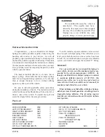
Safety airbag-28
SRS translation wiring harness
releases wring harness
shorting site
6m plus
the shroud
protection tube
Safety airbag module abandoning instruction
Carry out the operation according to the following procedure to abandon a safety airbag module or a vehicle with the SRS
safety airbag. First of all, release the safety airbag.
Unreleased safety airbag module abandoning
Caution
First release the SRS safety airbag when abdbdon it.
Release the safety airbag outside the vehicle to replace the safety airbag module.
Conduct the operation somewhere next to a smoke tester due to the smoke during the safety airbag’s release.
Tell the people to cover their ears and try to conduct the operation somewhere far away from the residential area due
to the big noise during the safety airbag’s release.
Remove the accumulator positive and negative and remove the accumulator off the vehicle.
Caution
Continue the operation 60 seconds after the removal of accumulator positive and negative.
Release the safety airbag module according to the following procedure.
1. Driver’s side safety airbag module
a. Remove the blocking lever
b. Remove the clock spring 2# joint and instrument panel wiring harness joint (yellow)(figure 8.6)
Caution
The clock spring joint will short automatically after the removal of clock spring from the instrument wiring harness,
which can prevent any possible major accident caused by the incorrect release of driver’s side safety airbag module duo
to the static interference from happening.
c. Connect the SRS safety airbag translation wring harness with 2 6m plus release wiring harnesses, wrap the joint part with
insulating tape for insulation.
Summary of Contents for hover
Page 1: ......
Page 27: ......
Page 34: ...Clutch 4 Cluchcontrolmechanism clutch master cylinder N m specified torque...
Page 84: ...Automatic transmission 8...
Page 91: ...Automatic transmission 15 Figure 3 6 Hydraulic control circulation flow...
Page 101: ...Automatic transmission 25 Figure 4 5 Parking mechanism...
Page 104: ...Automatic transmission 28 Figure 5 1 parking and neutral position...
Page 106: ...Automatic transmission 30 Figure 5 2 Reverse Gear...
Page 108: ...Automatic transmission 32 Figure 5 2 Reverse Gear...
Page 110: ...Automatic transmission 34 Figure 5 4 Automatic 1 st Gear...
Page 112: ...Automatic transmission 36 Figure 5 5 Automatic 2 nd Gear manual 2 nd Gear...
Page 114: ...Automatic transmission 38 Figure 5 6 Automatic 3 rd Gear manual 3 rd gear...
Page 116: ...Automatic transmission 40 Figure 5 7 Automatic 3 rd Gear locking and manual 3 rd Gear locking...
Page 118: ...Automatic transmission 42 Figure 5 8 Automatic 4 th Gear overspeed Gear...
Page 120: ...Automatic transmission 44 Figure 5 9 Automatic 4th Gear locking...
Page 154: ...Figure 8 39 Valve fixing plug and pin Figure 8 40 Torque converter release ball and spring...
Page 168: ...Annex Description for oil inlet hole of main housing...
Page 169: ...Chapter 6 Drive shaft...
Page 173: ...Chapter 7 Suspension and vehicle axle Rear suspension 112...
Page 176: ......
Page 178: ...h Check the sideslip Sideslip Within 5m km...
Page 318: ...Brake 32...
Page 321: ...Steering 2...
Page 322: ...Steering 3...
Page 323: ...Steering 4...
Page 325: ...Steering 6...
Page 326: ...Steering 7...
Page 327: ......
Page 330: ......
Page 331: ......
Page 332: ......
Page 333: ......
Page 334: ......
Page 335: ......
Page 336: ......
Page 337: ......
Page 338: ......
Page 339: ......
Page 340: ......
Page 341: ......
Page 342: ......
Page 343: ......
Page 344: ......
Page 345: ......
Page 346: ......
Page 347: ......
Page 348: ......
Page 349: ......
Page 350: ......
Page 352: ......
Page 353: ......
Page 354: ...CD Player and Air Conditioning System 1 Chapter 11 CD Player and Air Conditioning System...
Page 371: ...Safety airbag 1 Chapter 12 Safetyairbag...
Page 373: ...Safety airbag 3...
Page 425: ......


