


surface area; or, the hinge slots are very tight, restricting
the flow of CA to the back of the hinges. This results in
hinges that are only “tack glued” approximately 1/8" to 1/4"
into the hinge slots. The following technique has been
developed to help ensure thorough and secure gluing.
It is best to leave a very slight hinge gap, rather than closing
it up tight, to help prevent the CA from wicking along the
hinge line. Make sure the control surfaces will deflect to the
recommended throws without binding. If you have cut your
hinge slots too deep, the hinges may slide in too far, leaving
only a small portion of the hinge in the control surface. To
avoid this, you may insert a small pin through the center of
each hinge before installing. This pin will keep the hinge
centered while you install the control surfaces.
❏
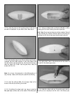
4. Insert the joiner wire through the fuse TE. Glue the
joiner wire in the elevator halves with 6-minute epoxy. Before
the epoxy cures, apply 6 drops of thin CA adhesive to both
sides of each hinge. Allow a few seconds between drops for
the CA to wick into the slot. Use a paper towel to wipe off
any excess CA that may have gotten onto the covering.
❏
5. Install the ailerons with their hinges, repeating the
gluing technique described previously.
❏
6. Wipe off the nylon tailwheel bearing with a paper towel
dampened with rubbing alcohol. Use 6-minute epoxy to glue
the tailwheel bearing in the aft end of the fuse. After the
epoxy has cured, pack the tailwheel wire hole in the rudder
with 6-minute epoxy. Install the rudder with its hinges.
Repeat the gluing technique described previously and allow
the epoxy to cure.
Hint: Apply a little petroleum jelly to the tail gear wire where
it passes through the nylon bearing. This will prevent the
wire from being glued to the bearing.
❏
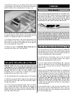
1. Install a 3/32" wheel collar (not included), a 1" tail wheel
(not included) and a second 3/32" wheel collar on the
tailwheel wire. Secure the wheel collars to the tailwheel wire
with 4-40 set screws (not included). Use thread locking
compound on the set screws to prevent them from loosening.
❏
2. Reinstall the landing gear on the fuse and the wheel
and wheel pants on the landing gear.
❏
1. Cut one of the #64 rubber bands into six 3/4" long
pieces. Hold the landing gear fairing to the landing gear, pull
the rubber band “straps” around the landing gear and glue
them to the covering on the bottom with thin CA. The top
forward rubber band strap goes over the landing gear and
the aft strap attaches to the fuse.
❏
2. Reinstall the engine and cowl.
❏
3. Assemble the fuel tank per the manufacturer's
instructions. Connect approximately 1' of fuel tubing to the
fuel pick-up fitting on the fuel tank and 1' of fuel tubing to the
pressure fitting on the tank. Wrap the fuel tank in 1/4" foam
rubber. If you are installing the fuel tank so it can be
Finish the Model
Install the Wheels
ASSEMBLE, THEN APPLY 6 DROPS
OF THIN CA TO CENTER
OF HINGE, ON BOTH SIDES
43