NOTE: The control throws are measured at the widest part
of the elevators, rudder and ailerons. It is likely that the
recommended rudder control throws will not be achieved by
adjusting the linkages mechanically (by changing the
position of the clevises on the servo arm). Instead, the
transmitter ATV will probably have to be used for this. The
ATV in the transmitter used to fly the prototypes was set to
70% to achieve the correct rudder throw.
NOTE: This procedure is not to be confused with balancing
the model (checking the C.G.). That important step will be
covered after this procedure.
❏
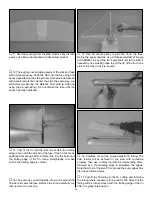
1. With the wing level, have an assistant help you lift the
model by the engine propeller shaft and the bottom of the
fuse under the trailing edge of the fin. Do this several times.
❏
2. If one wing always drops when the model is lifted, it means
that side is heavy. Balance the airplane by adding weight to the
other wing tip. An airplane that has been laterally balanced
will track better in loops and other maneuvers.
At this stage the model should be in ready-to-fly condition
with all of the systems installed including the engine, landing
gear, propeller and spinner and the radio system. The fuel
tank should be empty.
❏
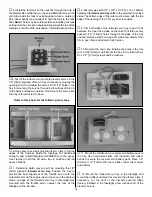
1. If using a Great Planes C.G. Machine
™
to balance the
model, set the rulers on the C.G. Machine to 4-3/16"
[106mm]. If you do not have a Great Planes C.G. Machine,
use a felt-tip pen or 1/16" to 1/8" [1.5 to 3mm] tape to
accurately mark the C.G. 4-3/16" [106mm] from the leading
edge next to both sides of the fuselage on the top of the wing.
❏
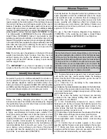
2. Mount the wing to the fuselage. If using a C.G.
Machine, place the model on the machine. If not using a
C.G. Machine, lift the model upside-down at the balance
point marked on top of both sides of the wing using the tip
of your middle finger on both hands.
This is where the model should balance for the first flights.
Later, you may wish to experiment by shifting the C.G. up
to 1/4" [6mm] forward or 1/4" [6mm] back to change the
flying characteristics. Moving the C.G. forward will
increase stability, but will decrease the model's aerobatic
capabilities by decreasing maneuverability. Moving the
C.G. aft will have the opposite effect. In any case, as long
as the model is balanced within the recommended
range it will not display any bad tendencies. Do not at any
time balance the model outside the recommended range.
More than any other factor, the C.G. (center of gravity, also
referred to as the balance point) can have the greatest
effect on how a model flies and may determine whether or
not your first flight will be successful. If you value this model
and wish to enjoy it for many flights, DO NOT OVERLOOK
THIS IMPORTANT PROCEDURE. A model that is not
properly balanced will be unstable and possibly unflyable.
Balance the Model (C.G.)
Balance the Model Laterally
We recommend the following control surface throws:
High Rate
Low Rate
ELEVATOR:
1" [25mm] up
3/4" [19mm] up
1" [25mm] down
3/4" [19mm] down
RUDDER:
1-9/16" [40mm] right 1-3/8" [35mm] right
1-9/16" [40mm] left
1-3/8" [35mm] left
AILERONS:
3/4" [19mm] up
1/2" [13mm] up
3/4" [19mm] down
1/2" [13mm] down
IMPORTANT: The balance point and control surface throws
listed in this manual are the ones at which the Ryan flies
best. Set up your aircraft to those specifications. If, after a
few flights, you would like to adjust the throws or C.G. to suit
your tastes, that is fine. Too much control surface throw can
make your model difficult to control or force it into a stall, so
remember “more is not always better.”
28


