20
❏
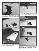
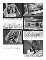
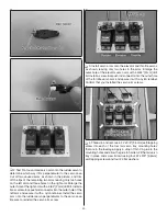
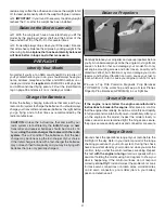
2. Test fi t a four-armed servo arm onto the rudder servo to
determine which way it fi ts perpendicular to the servo case.
Cut off two unused arms as shown in the picture, and trim
off the tips of the remaining two arms leaving only two holes
on the left arm and three holes on the right arm. Enlarge the
outer hole of the right arm with a 5/64" [2mm] drill bit. Install a
brass screw-lock pushrod connector into the outer hole of the
left arm and secure it with a nylon retainer. Install the servo
arm onto the rudder servo perpendicular to the servo case.
Be sure to reinstall the servo arm screw.
❏
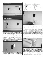
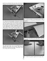
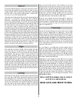
3. Install servo arms onto the elevator and throttle servos
as shown, leaving only two holes in the arms. Enlarge the
outer hole of the elevator servo arm with a 5/64" [2mm] drill
bit. Install a screw-lock pushrod connector into the outer hole
of the throttle servo arm and secure it with a nylon retainer.
Confi rm that you installed the servo arm screws.
❏
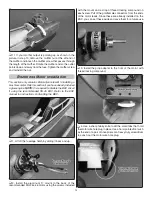
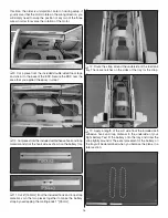
4. Thread in and remove a #2 x 3/8" [9.5mm] self-tapping
screw into each of the four tail servo tray mounting holes
that are in the fuselage. Apply a drop of thin CA glue to the
mounting holes and allow the glue to harden. Fit the tail servo
tray in place and screw it down using four #2 x 3/8" [9.5mm]
self-tapping screws and four #2 fl at washers.

