8
HOW TO SOLDER
1. Roughen the end of the pushrod with coarse sandpaper
where it is to be soldered. Use denatured alcohol or other
solvent to thoroughly clean the pushrod.
2. Apply a few drops of soldering fl ux to the end of the
pushrod, and then use a soldering iron or a torch to heat
it. “Tin” the heated area with silver solder by applying the
solder to the end. The heat of the pushrod should melt the
solder – not the fl ame of the torch or soldering iron – thus
allowing the solder to fl ow. The end of the wire should be
coated with solder all the way around.
3. Place the clevis on the end of the pushrod. Add another
drop of fl ux, then heat and add solder. The same as before,
the heat of the parts being soldered should melt the solder,
thus allowing it to fl ow. Allow the joint to cool naturally
without disturbing. Avoid excess blobs, but make certain
the joint is thoroughly soldered. The solder should be shiny,
not rough. If necessary, reheat the joint and allow to cool.
4. Immediately after the solder has solidifi ed, but while it
is still hot, use a cloth to quickly wipe off the fl ux before
it hardens.
Important:
After the joint cools, coat the joint
with oil to prevent rust.
Note:
Do not use the acid fl ux that
comes with silver solder for electrical soldering.
This is what a properly soldered clevis looks like –
shiny solder with good flow, no blobs and flux removed.
❏ ❏
13. Once the solder has cooled slide a silicone clevis
keeper over each clevis. Install the pushrod wire assembly to
the aileron servo arm and aileron control horn.
❏ ❏
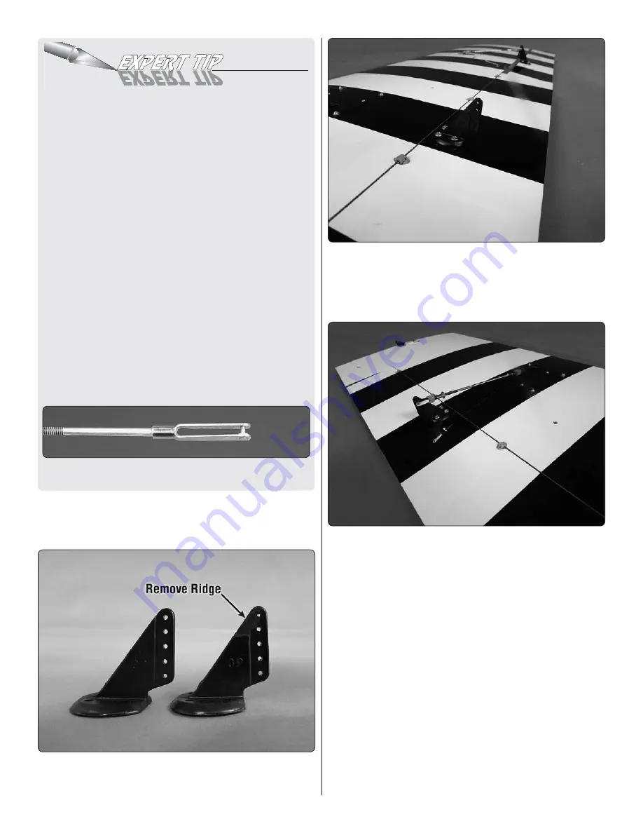
14. The flap control horn needs to be modified. Trim a
control horn as shown. A high speed motor tool works well
for this.
❏ ❏
15. Install the modified control horn to the flap. However,
the flap horn is rotated 180° from the direction the aileron
horn was installed. Install the horn using the same method
used for the aileron. Make sure the base of the horn is even
with the flap leading edge.
❏ ❏
16. Screw the 4-40 nut and the threaded metal clevis
onto the pushrod wire. Attach the clevis to the second hole
down on the control horn. Attach the metal solder clevis into
the outer hole of the flap servo arm. For the flap servo you
will not center the servo. Instead, make sure the flap is fully
closed to the bottom of the wing. Then position the servo arm
so that it is rotated toward the wing trailing edge. Now you can
proceed with making the pushrod wire assembly.
Mark on the pushrod wire where to cut the wire. Remove
all of the pushrod wire components. Solder the metal solder
clevis to the pushrod. Once the solder has cooled slide a
silicone clevis keeper over each clevis. Install the pushrod
wire assembly to the servo arm and control horn.
❏
17. Repeat steps 1-16 for the right wing.


