background image


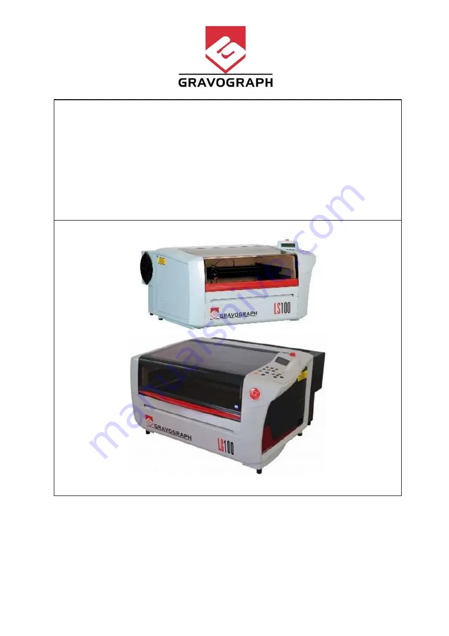
NOTICE TECHNIQUE LS100 

LS100 TECHNICAL MANUAL 

Date : June 2009 From 

Aftersales Technical Support 

Ref. LS100 GB/FF     -     Vers. 1.0


Page 1 


Servicing Manual 

Manuel Technique 


LS100  machine V1 & V2 

Machine LS100 V1 et V2


English – 

French 


September  2011 from After Sales Technical Support 


Summary of Contents for LS100 V1

Page 1: ...ICAL MANUAL Date June 2009 From Aftersales Technical Support Ref LS100 GB FF Vers 1 0 Page 1 Servicing Manual Manuel Technique LS100 machine V1 V2 Machine LS100 V1 et V2 English French September 2011...

Page 2: ...IMIT SWITCH FIN DE COURSE Z page 53 LS100 16 Z AUTO LIMIT SWITCH FIN DE COURSE AUTO Z page 55 LS100 17 Z AUTO FOCUS BAR BARRE AUTO FOCUS page 58 LS100 18 Z MOTOR MOTEUR Z page 61 LS100 19 Z BELT COURR...

Page 3: ...6 TICKLE ADJUSTMENT REGLAGE TICKLE page 144 UPDATED LS100 A07 ALIGNMENT MODE MODE ALIGNEMENT page 148 CHARACTERISTICS CARACTERISTIQUES LS100 T01 CHARACTERISTIC CARACTERISTIQUES page 150 LS100 T02 FIRM...

Page 4: ...SYSTEM 15332 Y STEPPER MOTOR SIMPLE SHAFT 15352 20 40 60W T60 INTERFACE BOARD 22930 LCD SCREEN KIT 23542 X Y AXIS SLEEVE 24297 LS 30 LENS COTTON BUD WALLET 26327 CLEANING KIT G1 G2 1 26530 LASER SAFE...

Page 5: ...46260 Y MOTOR DOUBLE SHAFT KIT OBSOLETE 46261 ELECTRONIC RACK WIRING LOOM 46262 MACHINE WIRING LOOM 46263 INTERFACE DISPLAY BOARD 46265 CABLED DOOR SENSOR 1 46373 UC USB BOARD 32Mo 1 46559 OBSOLET STD...

Page 6: ...MIRROR SUPPORT CALIPER MACHINE 48894 AUTO FOCUS Z AXIS LS100 KIT 2 48943 HEAD SUPPORT LS100 49056 Y MOTOR RETROFIT KIT 49097 PRESEPARATOR REPLACEMENT BAG 49113 COMPLETE WIRING LOOM RACK MACHINE 49296...

Page 7: ...ire glisser l axe droit vers l int rieur pour le dissocier du b ti Move the left axis towards inside in order to separate it from the frame Faire glisser l axe gauche vers l int rieur pour le dissocie...

Page 8: ...Place the left and right ways spring into the springs Placer les axes de guidage droit et gauche dans les ressort Place the door correctly by lifting it up and by pushing towards the bottom Placer la...

Page 9: ...the frame Faire glisser l axe droit vers l int rieur pour le dissocier du b ti Move the left axis towards inside in order to separate it from the frame Faire glisser l axe gauche vers l int rieur pour...

Page 10: ...e left and right ways spring into the springs Placer les axes de guidage droit et gauche dans les ressorts Place the door correctly by lifting it up and by pushing towards the bottom Placer la porte c...

Page 11: ...l acc s aux diff rents l ments Unscrews the 4 screws located inside the machine Desserrer les 4 vis plac es l int rieur de la machine Remove the front plate by lifting it up Retirer la t le avant en l...

Page 12: ...its plate holder by 2 screws Enlever le capteur de son support par les 2 vis Assembling operation Op ration de remontage Right side sensor Detecteur cot droit Place the sensor on its holder to the li...

Page 13: ...econnecter les 2 connecteurs Replace the front plate Replacer la t le avant Tight the 4 screws located inside the machine Resserrer les 4 vis plac es l int rieur de la machine This operation is finish...

Page 14: ...e de la machine par les 2 vis To loosen the table screws lock the bottom Screw with a flat spanner 17mm then to loosen the top Screw Pour desserrer les crous de table bloquer l crou inferieur avec une...

Page 15: ...le de gravure sur l crou de la vis guide In order to make easier the flatness adjustment of the table we suggest you to make a preliminary adjust of the brass screws Afin de faciliter le r glage de pl...

Page 16: ...distance de focale Laisser s cher quelques minutes Make the flatness adjustment of the engraving table see chapter LE100 34 Proc der au r glage de plan it de la table voir chapitre LE100 34 Put back...

Page 17: ...tion gauche sur le pont puis d poser les vis de droite du guidage and then put the head on the left side to remove the screw which are on the right Keep the center screw for the moment puis d placer l...

Page 18: ...omber le chariot mobile Si le chariot est retir du guidage il sera inutilisable Put back the new X guide way on the bridge and then put all fixing screws without tightening Replacer le nouveau guidage...

Page 19: ...tenant serrer les 2 vis de la t te Check the flatness table and adjust it if necessary See chapter LS100 034 Contr le de plan it table ajuster si n cessaire Voir chapitre LS100 034 This operation is f...

Page 20: ...icit e poulie axe moteur 0 1mm Dismantling operation Op ration de d montage Remove the right side casing 4 nuts Retirer le carter droit par ses 4 vis Remove the left side of the machine by 2 screws in...

Page 21: ...easier the extraction of X motor Pousser l g rement sur la courroie pour la d tendre la poulie du moteur et facilit le l extraction du moteur X Pull the x motor up to move take it away from the bridg...

Page 22: ...id to pinch them and make short circuit Avant de remettre en place le cache connecteur X bien contr ler la position des fils d alim moteur afin d viter de les pincer et provoquer un court circuit Put...

Page 23: ...the screw Placer le clavier sur la machine de fa on ce que la patte de maintien soit correctement plac e puis serrer la vis Put back the right housing then tight the 4 screws Replacer le carter droit...

Page 24: ...ht side of the bridge Couper les2 colliers de fixation fixations faisceau et tuyau air situ s gauche et au centre du pont Do not damage air pipe and wiring loom Assurez vous de ne pas endommager le fa...

Page 25: ...out in order to remove it from its support Tirer l g rement le fin de course pour le faire sortir de son support Loosen the 2 screws and remove the plate holder Desserrer les 2 vis et retirer la plaq...

Page 26: ...t the X limit switch Reconnecter le faisceau Put back the limit switch wire in the wiring loom protection housing Replacer le faisceau du fin de course dans le capot de protection faisceau Put back th...

Page 27: ...central plastic clamp to avoid compressing the air pipe Placer le collier de gauche sur le raccord d air et le ne serrer pas trop fort le collier central pour ne pas comprimer le tuyau Put back the l...

Page 28: ...situ gauche de la machine l extr mit du pont X Loosen each 2 screws of 4 tours and push them to right side in order to unbend the X belt Desserrer les 2 vis de 4 tours chacun et poussez les vers la d...

Page 29: ...Une bande dans la longueur et une bande entourant la courroie suffisent Pull slightly the belt by hand and follow the movement with the other hand until the new belt make a complete revolution of the...

Page 30: ...serrer les 2 vis de chaque attache droite et gauche Tight the 2 screws to get the tension of the belt Resserrer les 2 vis pour obtenir la tension de la courroie Tight the 2 screws 4 turn to get the te...

Page 31: ...ier si la courroie est correctement align e d placer la t te de droite gauche Pendant ce d placement regarder la sortie du tendeur que la courroie se d place lin airement et aligner par rapport a sa p...

Page 32: ...rassement Remove the 2 screws of the head mirror D poser le miroir de t te par 2 vis Reassembling operation Op ration de remontage Put back the head mirror in its place Remettre le miroir sur son empl...

Page 33: ...es de l ancien moteur pas pas Y double axes qui est directement fix aux barres d entra nement Y voir photo ci dessous Ce moteur est maintenant obsol te si vous devez le changer il faut monter le nouve...

Page 34: ...of the motor holder and loosen the screw of the back Retirer la premi re vis du support et desserrer la vis du fond Make revolve the motor holder to free the axis and remove the back screw Faire pivot...

Page 35: ...ck plate then dissociate them Retirer les 4 vis de fixation moteur de la platine puis d solidariser l ensemble Remove the pulley from the motor axis Retirer la poulie de l axe moteur Use a screwdriver...

Page 36: ...screws of the pulley holder Resserrer les vis du support poulie Tight the 2 screws of the coupling Resserrer les 2 vis de l accouplement Put back the motor on the support and place the belt Replacer l...

Page 37: ...2 accouplements dans les axes et serrer les 4 vis As the coupling has been loosed the squareness of the bridge is perhaps not correct It is necessary to process to a new adjustment L accouplement mote...

Page 38: ...ouge l axe moteur ne doit pas bouger Make a new squareness checking by moving the set square to the left and right side of the X Bridge Faire un nouveau contr le d querrage en d pla ant l querre droit...

Page 39: ...sheet metal of the machine by unscrewing the 2 screws Retirer la t le gauche de la machine par les 2 vis The limit switch connector is located to the left back of the machine Le connecteur du fin de...

Page 40: ...r les vis Put back the X limits switch plate holder on the machine than tight the screws Replacer le support du fin de course sur la machine suivant le rep re puis serrer les vis Before tightening the...

Page 41: ...gauche de la machine proc der au r glage du point z ro Voir chapitre LS100 38 Si le d placement avec les fl ches ne permettent pas un r glage parfait alors d placer le support de fin de course vers l...

Page 42: ...bridge in order to remove the back protective cover D placer the pont X vers le devant avant de d poser la t le de protection arri re Unscrew without to remove them the 2 screws of the motor plate De...

Page 43: ...a droite contre l paulement Move lightly the axis to remove the belt D placer l g rement l axe pour retirer la courroie Reassembling operation Op ration de remontage Put back the belt by sliding it be...

Page 44: ...t square top position against the X rule If set square is not anymore in contact with the bridge or with the X rule you must adjust the bridge angular D placer l querre le long du pont X en v rifiant...

Page 45: ...n if necessary Faire un essai de gravure avant le montage des carters Refaire un r glage de la tension de courroie l aide du bouton noir si n cessaire Put back the back protective plate by 2 screws Re...

Page 46: ...hine Retirer la t le droite de la machine par les 2 vis Loosen the locking screw of the belt tensioning idler Desserrer la vis frein du tendeur de courroie Loosen the two screws of the right coupling...

Page 47: ...t with the other hand until the new belt make a complete revolution of the bridge then remove the adhesive tape Tirer doucement la courroie d une main et accompagner le mouvement avec l autre main jus...

Page 48: ...err le pont n est plus d querre il faut donc proc der un nouvel querrage Place a set square against the X rule at the left side of the Y Bridge and move it in order to touch the top part of the square...

Page 49: ...r l accouplement en vous assurant que l axe d entrainement du guide droit Y ne tourne pas Make a new squareness checking by moving the set square to the left and right side of the X Bridge Faire un no...

Page 50: ...est d mont et remont La proc dure pour le tendeur de gauche est identique Remove the right side sheet metal of the machine by unscrewing the 2 screws Retirer la t le droite de la machine par les 2 vi...

Page 51: ...sous trouvant sous la poulie et retirer l crou de tension Reassembling operation Op ration de remontage Put back the tension nut Replacer l crou de tension Put back the belt tensioning idler by the sc...

Page 52: ...locage du tendeur Put back the inside right housing and tight the 4 screws Remettre en place le carter droit et le serrer par 4 vis To Put back the right side sheet metal tilt it slighty than insert t...

Page 53: ...ame Le fin de course est localis en bas gauche de la trappe Cut the 2 plastic collars to free the wiring loom Couper les 2 colliers plastique pour lib rer le faisceau Disconnect the connector without...

Page 54: ...plastique utiliser le per age central du support Put back the clip holder and tight the screw Remettre en place le support collier et serrer la vis Put back the left sides of the machine then fix it b...

Page 55: ...a t le gauche de la machine par les 2 vis Remove the protection cap of the cylindrical attachment connector Retirer le bouchon de protection du connecteur tourne cylindre Remove the left housing in or...

Page 56: ...er la d connexion Remove the Z auto limit switch by 2 fixing screws Retirer le fin de course en d vissant les 2 vis Reassembling operation Op ration de remontage Replace the Z auto limit switch and ti...

Page 57: ...faisceau et serrer les 2 vis Make this operation easier angled lightly the wiring loom protection housing than push it in right Pour facilit la mise en place incliner l g rement le capot de protectio...

Page 58: ...ur le pont se trouvant gauche et au centre du pont Do not damage the air pipe and the wiring loom Assurez vous de ne pas endommager le faisceau et le tube d air The Auto Z bar is fixed by 2 points lef...

Page 59: ...lever l g rement la barre Z auto puis ins rer une fine tige tournevis fin dans le taraudage de l axe pivot et le tirer Remove the bar by shifting it to the back and lifting it up lightly Retirer la ba...

Page 60: ...pas endommager la lamelle du fin de course lors du serrage des vis Put back the 2 plastic clamps to lock the wiring loom Remettre en place les 2 colliers plastiques pour maintenir le faisceau Place a...

Page 61: ...e of the Z motor D poser la platine support faisceau par la vis droite du moteur Cut the plastic clip of the wire holder plate Couper le collier de maintien du faisceau Disconnect the z motor connecto...

Page 62: ...ve the belt from the pulleys D gager la courroie des poulies Remove le Z motor plate by 2 screws D poser la platine moteur par ses 2 vis To remove the Z motor make a rotation of 45 in th e clockwise w...

Page 63: ...errer les 2 vis Place back the belt around pulleys Replacer la courroie autour des poulies To tight the belt press vertically on the belt tensioner and tight the screw Pour tendre la courroie exercer...

Page 64: ...ier de maintien du faisceau Put back the wire plate holder the right side by the screw located at the right side of the Z motor Replacer la platine support faisceau par la vis droite du moteur Make an...

Page 65: ...is strongly recommended to place a protection to protect the left side of the laser Remarque cette op ration va n cessiter de mettre la machine sur le flan Il est donc fortement recommander de placer...

Page 66: ...fter tighten the belt tensioner check the tension of the belt by pressing on it To be correct there is a small gap About 1 5 cm or 2 cm Too much tightened there is a risk of locking of the table Apr s...

Page 67: ...eration we recommend you to move down the engraving table to the bottom position Pour cette op ration nous vous conseillons de descendre la table de gravure en position basse Remove the right side of...

Page 68: ...tirer les 2 vis du palier de roulement de la vis Z Nota the operation requires putting the machine on the side it is strongly recommended to place a protection to protect the left side of the laser Re...

Page 69: ...vis sans fin Z par l int rieur du laser The 2 screws located at each side of the bearing are a mechanic limit for bearing it is not necessary to remove them Les 2 vis plac es de chaque cot du rouleme...

Page 70: ...pull it to the mechanic limit 2 screws Replacer le roulement dans son emplacement par l int rieur du laser et enfonc le jusqu la but e m canique 2 vis Put back the Z leadscrew and insert the extremit...

Page 71: ...ten it Replacer la poulie sur l axe de la vis sans fin aligner l extr mit de la vis avec la partie plate de la poulie puis serrer Put back the belt around pulleys Replacer la courroie autour des pouli...

Page 72: ...e et remonter la pr s du palier Tighten the shaft by 2 screws Serrer les 2 vis du palier Make an up and down test of the engraving table Faire un essai de monte et baisse de la table At this stage it...

Page 73: ...e the right side sheet metal of the machine by the 2 screws Retirer la t le droite de la machine par les 2 vis The right mirror is located at the extremity of the bridge Le miroir de renvoi et situ l...

Page 74: ...placing the 2 elastomer parts at the top and bottom position Remettre en place le miroir en pla ant les 2 pi ces en lastom re en position haute et basse Tight the 4 screws up to feel the resistance o...

Page 75: ...unnel Retirer le tunnel d aspiration Tear down the 4 electronic rack screws located left right of electronic rack D poser les 4 vis du rack lectronique situ es de chaque cot du rack and then pull the...

Page 76: ...onnecteur de la carte s curit Disconnect the Laser interface board connector this cable is connected to the laser tube D connecter le connecteur de la carte interface Laser Ce c ble est reli la source...

Page 77: ...et du rack lectronique Reassembling operation Op ration de remontage Connect the connector MOTEURS of the power board Reconnecter le connecteur MOTEURS de la carte de puissance Push in correctly the c...

Page 78: ...ard Reconnecter le connecteur fin de course shutter machine en haut droite de la carte de puissance Connect the interface board connector Reconnecter le connecteur de la carte interface Connect the sa...

Page 79: ...he machine Placer le rack lectronique correctement sur les guides droit et gauche puis pousser le rack l int rieur de la machine Place exhaust pipe in the rack and fix it with the screw you can put yo...

Page 80: ...e puis tirer le rack vers l ext rieur Tirer le rack lectronique For facility disassembling leave enough space between the electronic rack and the frame for sliding your hand Pour facilit le d montage...

Page 81: ...onic rack correctly on right and left on the guide and then slide the rack in the machine Placer le rack lectronique correctement sur les guides droit et gauche puis pousser le rack l int rieur de la...

Page 82: ...pes de sources les source Synrad et source Coherent La source Synrad uniquement 30W et 40W sur LS100 n cessite un seul bloc d alimentation dont la tension de sortie est de 27V La source Coherent de 30...

Page 83: ...supply holder by unscrewing the 4 screws D poser le support de l alimentation tube laser en retirant les 4 Vis Reassembling operation Op ration de remontage Put back the power supply holder with 4 scr...

Page 84: ...ser le rack l int rieur de la machine Place exhaust pipe in the rack and fix it with the screw you can put your hand inside in order to push wires to avoid to pinch them Placer le tuyau d extraction d...

Page 85: ...t Disconnect the main power cords connected to laser tube power supply 2 black 2 white 2 yellow green D connecter les fils d alimentation secteur connect l alimentation source 2 noir 2 blanc 2 jaune v...

Page 86: ...c alimentation que vous devez changer Remove the 3 screws to take off one of the concerned power supply Retirer les 3 vis de fixation afin de d poser l alimentation concern e Dual unit reassembling op...

Page 87: ...ght and left on the guide and then slide the rack in the machine Placer le rack lectronique correctement sur les guides droit et gauche puis pousser le rack l int rieur de la machine Place exhaust pip...

Page 88: ...te UC Dismantling operation Op ration de d montage Remove the electronic rack see Chapter LS100 22 and then remove laser control board see chapter LS100 30 D poser le rack lectronique Voir chapitre LS...

Page 89: ...faisceau du panneau de control sur la carte UC Put back the laser control board and e rack see chapter LS100 33 and LS100 22 Replacer la carte laser contr le puis le rack lectronique voir chapitre LS1...

Page 90: ...connecteurs nous recommandons de ne pas tirer sur les fils afin d viter tout risque de mauvais contact Remove the exhaust tunnel Retirer le tunnel d aspiration Tear down the 4 electronic rack screws...

Page 91: ...to the connectors Be sure that they are correctly connected Replacer la carte s curit en la poussant vers le connecteur Assurez vous que les connecteurs soient correctement enfich s Warning be sure th...

Page 92: ...hand inside in order to push wires to avoid to pinch them Placer le tuyau d extraction dans le rack puis le fixer l aide de la vis vous pouvez mettre votre main l int rieur afin de repousser les fils...

Page 93: ...slightly the source housing to disconnect the fan wire Attention Tirer le carter de source l g rement pour pouvoir d connecter le faisceau du ventilateur Unscrew a little bit the plastic tunnel 4 scre...

Page 94: ...d connecter Disconnect the red pointer wire D connecter le faisceau du pointeur rouge Unscrew the 4 main screws of the aluminium locking D visser les 4 vis principale des pattes de maintien de la sou...

Page 95: ...a base de la source repose sur les vis d alignement de la source Put back the 4 aluminum locking on the laser source plate holder Replacer les 4 pattes sur la t le support source Place the 4 aluminum...

Page 96: ...Beam alignment see chapter LS100E 35 Tickle adjustment see chapter LS100 40 Alignment mode see chapter LS100 41 A ce stade vous devez proc der aux diff rents r glages de la source Premi re tape Aligne...

Page 97: ...mauvais contact Unscrew the source housing by 4 screws and then tear down it D visser les 4 vis du carter de source Puis le d poser Disconnect the data cable from laser control board to laser tube RJ4...

Page 98: ...e Disconnect the red pointer D connecter le pointeur rouge Disconnect the FAN board sensor and then remove the screw to tear down it D connecter le capteur de la fan board puis r tirer la vis de fixat...

Page 99: ...ling operation COHERENT TUBE Op ration de remontage Put back the laser source on the machine Repositionner la source laser sur la machine Make sure that the source frame base is correctly place on the...

Page 100: ...hen remove the screw to tear down it Connecter le capteur de la fan board puis retirer la vis de fixation pour d poser la sonde Fix the cords sensor fan board red pointer along the laser tube with pla...

Page 101: ...roit et gauche puis pousser le rack l int rieur de la machine Place exhaust pipe in the rack and fix it with the screw you can put your hand inside in order to push wires to avoid to pinch them Placer...

Page 102: ...chapter LS100E 35 Tickle adjustment see chapter LS100 40 Alignment mode see chapter LS100 41 A ce stade vous devez proc der aux diff rents r glages de la source Premi re tape Alignement faisceau Voir...

Page 103: ...the interface board See chapter LS100 29 Retirer la carte interface laser Voir chapitre LS100 29 Remove the safety board See chapter LS100 26 Retirer la carte s curit laser Voir chapitre LS100 26 Remo...

Page 104: ...from the UC board pull it up slightly and pull it at the right side then take it out of the frame Pour d connecter la carte puissance de la carte UC la soulever l g rement et la tirer droite puis la s...

Page 105: ...oard See chapter LS100 29 Remettre la carte interface laser Voir chapitre LS100 29 Put back the safety board See chapter LS100 26 Remettre la carte s curit laser Voir chapitre LS100 26 Put back the cy...

Page 106: ...RFACE LASER BOARD CARTE INTERFACE LASER 64913 E7606 V30 ONLY FOR 30W SYNRAD This new laser interface board is compatible with all powers and models laser tubes There is a jumper to select the laser tu...

Page 107: ...er le tunnel d aspiration Tear down the 4 electronic rack screws located left right of electronic rack D poser les 4 vis du rack lectronique situ es de chaque cot du rack and then pull the rack outsid...

Page 108: ...fting up it Retirer la carte interface en la soulevant Reassembling operations Op ration de remontage Put back the interface board by pushing it Replacer la carte interface en la poussant Nota Make su...

Page 109: ...ser le rack l int rieur de la machine Place exhaust pipe in the rack and fix it with the screw you can put your hand inside in order to push wires to avoid to pinch them Placer le tuyau d extraction d...

Page 110: ...unnel Retirer le tunnel d aspiration Tear down the 4 electronic rack screws located left right of electronic rack D poser les 4 vis du rack lectronique situ es de chaque cot du rack and then pull the...

Page 111: ...arning Do not tilt the board to remove it you could damaged the interface connector Attention ne pas incliner la carte pour la retirer vous pourriez d t riorer le connecteur inter carte Reassembling o...

Page 112: ...ser le rack l int rieur de la machine Place exhaust pipe in the rack and fix it with the screw you can put your hand inside in order to push wires to avoid to pinch them Placer le tuyau d extraction d...

Page 113: ...la vis de la plaque de maintien du clavier et le retirer en la glissant puis le soulevant The 2 air assist pipes are marks with colored stickers Yellow and green It is important to respect those mark...

Page 114: ...r les couleurs pour chaque tube Place the control panel on the machine so that the he top door correctly by lifting it up and by pushing towards the bottom then tight the screw Placer le clavier sur l...

Page 115: ...left right of electronic rack D poser les 4 vis du rack lectronique situ es de chaque cot du rack and then pull the rack outside the machine puis tirer le rack vers l ext rieur Tirer le rack lectroni...

Page 116: ...the rack in the machine Placer le rack lectronique correctement sur les guides droit et gauche puis pousser le rack l int rieur de la machine Place exhaust pipe in the rack and fix it with the screw...

Page 117: ...ommandons de ne pas tirer sur les fils afin d viter tout risque de mauvais contact Remove the exhaust tunnel Retirer le tunnel d aspiration Tear down the 4 electronic rack screws located left right of...

Page 118: ...multan ment Reassembling operation Op ration de remontage Put back the CA board by pushing it Replacer la carte TC en la poussant sur ses cot s In which direction The capacitor on CA board is near the...

Page 119: ...hand inside in order to push wires to avoid to pinch them Placer le tuyau d extraction dans le rack puis le fixer l aide de la vis vous pouvez mettre votre main l int rieur afin de repousser les fils...

Page 120: ...frame La platine support de lampe est positionn e en haut du b ti Unscrew the 2 screws which maintain the lamp holder D visser les 2 vis maintenant le support ampoule Separate the lamp holder from the...

Page 121: ...ht back side Replacer la t le support l int rieur du carter La r sistance jaune est positionn e en bas droite Tight the 2 screws of lamp holder on the left housing Resserrer les 2 vis de la platine la...

Page 122: ...ampe est positionn e en haut du b ti Unscrew the 2 screws which maintain the lamp holder on the left housing D visser les 2 vis maintenant le support ampoule sur le carter int rieur gauche Separate th...

Page 123: ...s correctly locked Assurez vous de la bonne remise en place du verrou Reconnect the 2 connectors Reconnecter le faisceau de la lampe Attach the lamp wires with plastic collar Fixer le faisceau avec un...

Page 124: ...ches vers le bas et vers la droite Place a focal rod between the lens and the table and adjust the distance by using the up and down arrows in the Z function Then move the rod under the lens while tr...

Page 125: ...er front of the third Z leadscrew and check the distance with the focal rod Make the same test and adjustment than before D placer la t te laser au coin inf rieur gauche devant la troisi me vis Z et v...

Page 126: ...remplacement ou d montage de la source laser When the laser tube is fixed to the machine see chapter LS100 XX switch ON the machine then set the alignment mode as explain follow Quand la source est f...

Page 127: ...o make a laser beam shoot Appuyer sur quelques secondes pour faire un tir du faisceau laser Move the bridge to the front machine then push again on to make another laser beam shoot D placer le pont ve...

Page 128: ...NOTICE TECHNIQUE LS100 LS100 TECHNICAL MANUAL Date June 2009 From Aftersales Technical Support Ref LS100 GB FF Vers 1 0 Page 128...

Page 129: ...NOTICE TECHNIQUE LS100 LS100 TECHNICAL MANUAL Date June 2009 From Aftersales Technical Support Ref LS100 GB FF Vers 1 0 Page 129...

Page 130: ...same place of shoot 1 Dans ce cas vous devez serre les vis 1 2 pour aligner le shoot 2 au m me endroit que le shoot 1 Now you have to move up the laser tube in order to put the laser beam to the cente...

Page 131: ...side Positionner la t te cot droit Push on the key a few seconds in order to make a laser beam shoot Appuyer sur quelques secondes pour faire un tir du faisceau laser Move the head at the middle of t...

Page 132: ...adjust it in using the mirror located on the right side on the X bridge Pour ajuster le faisceau au centre de la cible centre lentille vous devez l ajuster l aide du miroir de gauche sur le pont X Mir...

Page 133: ...e droite sur pont X voir chapitre LS100 21 Remove the lens from the head Retirer la lentille de la t te Put a target in the head see p n in Viewer Installer un cible dans le t te voir ref dans Viewer...

Page 134: ...gl au centre de la cible d placer la t te sur le c t gauche puis effectuer un tir laser pour voir la position du faisceau On the left side if there is no visible shoot on the target this is because th...

Page 135: ...r est correctement align au centre de la cible d placer nouveau la t te en position droite afin de contr ler le bon alignement du faisceau dans les 2 positions Affiner le r glage si n cessaire Miroir...

Page 136: ...mplacement de la diode rouge Unscrew the source housing by 4 screws and then tear down it D visser les 4 vis du carter de source Puis le d poser Remove the right side sheet metal of the machine by uns...

Page 137: ...r un morceau d adh sif sur la table afin de facilit le r glage du pointeur rouge et d placer la t te au dessus Push on the key a few seconds in order to make a laser beam shoot Appuyer sur quelques se...

Page 138: ...ew the source housing by 4 screws and then tear down it D visser les 4 vis du carter de source Puis le d poser Remove the right side sheet metal of the machine by unscrewing the 2 screws Retirer la t...

Page 139: ...it se d placer au centre de la table pour effectuer le r glage Switch on the machine and when the GRAVOGRAPH message appears press on the X key Mettre sous tension la machine et l apparition du messag...

Page 140: ...fin de course Z auto Place the rod between the table and the lens Placer la pige entre la t te laser et la table Moves up the table with the Up arrow so that the rod comes in contact with the holder l...

Page 141: ...0 GB FF Vers 1 0 Page 141 Once the focal distance then validate by the key The head goes back at the origin Une fois la distance de focale r gl e presser sur la touche pour valider La t te retourne al...

Page 142: ...uyer sur la touch X quand le message GRAVOGRAPH apparait l cran LCD After this operation the head goes back to the left corner origin and the LED is ON Apr s cette op ration la t te laser retourne l o...

Page 143: ...late with the directional keys Ajuster le pointeur rouge du laser sur le coin de cette plaque l aide des touches directionnelles One the zero point adjusted validate by the key keep on the key until t...

Page 144: ...e Pas avant pas apr s mais exactement au premier point de marquage avec la puissance demand e La valeur d ajustement du tickle est sauvegard e dans la carte UC pour cette raison si vous devez changer...

Page 145: ...Click droit sur LSolution puis selectionner Printer Properties Click on About to access to LS solution driver tools then click on the LS machine picture Clic sur A propos pour acc der aux outils du dr...

Page 146: ...de voir toutes les impacts du faisceau The lines 9 and 8 are not OK perhaps the line 6 but if you look across the plexy with light you will see an beam impact on the line 7 but not front of 6 so 6 is...

Page 147: ...line 6 and then Push on key to validate the value Maintenant vous devez l aide des touches fl ches entrer la valeur de la ligne du tickle correspondant la premi re ligne grav e sans d faut dans notre...

Page 148: ...n doute sur la qualit de gravure pas pr cis d form s etc etc proc der au contr le et ajustement de ces param tres Connect the machine to PC then switch ON the machine and wait for Ready to receive mes...

Page 149: ...send test file button to send the alignment mode file to the machine Dans cette nouvelle fen tre cliquer sur le bouton Send Test file afin d envoyer le fichier vers la machine Now check each line in o...

Page 150: ...630 mm 33 x 35 4 x 24 8 in Net Weight Poids net Max 43 Kg 94 6 lbs Max 45 Kg 99 lbs Shipping weight Poids emballage machine Max 66 Kg 145 lbs Max 68 Kg 150 lbs Table surface Surface de la table 506 x...

Page 151: ...idit relative en utilisation 5 85 Electrical characteristics Caract ristiques lectriques 30 40 W 100 240 V 55 W 120 240V Input voltage Tension d entr e V 100 240 120 240 Max Amperage draw Amperage Max...

Page 152: ...diameter 100 mm 4 in LS100 et LS100Ex Minimum air flow required General Flux d air exig 0 5 kPa 200 m3 h Minimum air flow required with preseparator Flux d air exig avec pr s parateur 6 kPa 300 m3 h F...

Page 153: ...NOTICE TECHNIQUE LS100 LS100 TECHNICAL MANUAL Date June 2009 From Aftersales Technical Support Ref LS100 GB FF Vers 1 0 Page 153...

Page 154: ...NOTICE TECHNIQUE LS100 LS100 TECHNICAL MANUAL Date June 2009 From Aftersales Technical Support Ref LS100 GB FF Vers 1 0 Page 154...

Page 155: ...n LCD SETUP FPGA 2 0 GRAVOGRAPH PROG 2 91 LCD SOFT 1 0a 32 M BOOT 1 2 READY TO RECEIVE PARAMETERS FILE INFO CONFIGURATION POWER 0 SPEED 0 DPI_X 0 DPI_Y 0 Job parameters information Information des par...

Page 156: ...e S lectionner le type de machine PARAMETERS FILE INFO CONFIGURATION L SOLUTION 900XP LANGUAGE ENGLISH SERIAL PORT DISPLAY UNIT MM ENGLISH FRENCH GERMAN ITALIAN Select the language S lectionner le lan...

Page 157: ...en adjust IN OUT in order to drive an external S lectionner AUTOMATE ON afin de configurer les IN OUT pour piloter automatiquement une p riph rie compresseur externe PARAMETERS FILE INFO CONFIGURATION...

Page 158: ...uvegard s dans la m moire ce l UC QUEUE All Jobs sent to machine anre engraved step by step each START key Tous les job envoy s la machine sont graves les uns apr s les autre chaque pression de START...

Page 159: ...S DUAL HEAD OFF SET LASER TYPE This menu is only for information nothing to adjust SET LASER TYPE Ce menu est uniquement pour information rien configurer SET LASER TYPE TICKLE RE ALIGN MACHINE USING T...

Page 160: ...Ajustement coin gauche Voir chapitre LS100 A05 SET LASER TYPE TICKLE RE ALIGN MACHINE USING TIME XX RE ALIGN X Y RE ALIGN Z ALIGNMENT MODE RE ALIGN Z JOYSTICK Z 20 Z AUTO FOCUS adjustment See chapter...

Page 161: ...temps des job grav s TICKLE RE ALIGN MACHINE USING TIME XX SHUTTER COTROL OFF SHUTTER CONTROL Always OFF on LS100 CONTROL SHUTTER Toujours en position OFF sur LS100 RE ALIGN MACHINE USING TIME XX SHUT...

Page 162: ...nd ce message appara t et la LED rouge sur la carte PUI est allum e o Mettre la machine hors tension puis d connecter le connecteur d alimentation moteur de la carte PUI o Mettre nouveau la machine so...

Page 163: ...top of the cooling tunnel exchange if it is faulty o Quand ce message appara t et la LED jaune sur la carte PUI est allum e o Contr ler la rotation du ventilateur de la PUI Fixe l extr mit du tunnel...

Page 164: ...chine sans d connecter le faisceau puis l aide d un voltm tre contr ler la tension de sortie de des l alimentation s de source 48V 0 0 2 coherent 27V Synrad o Avec les sources Coherent 55W 60W 70W il...

Page 165: ...is a data cable between the laser tube and the laser control board Laser tube side it is 9 pins DIN connector interface board side it is a rectangular connecter Check connection each side o Sur les 3...

Page 166: ...la connectique est similaire si vous ne connecter pas la bonne carte le message d erreur 02 apparaitra l cran LCD lors de la mise sous tension Ce probl me peut arriver quand vous devez changer la cart...

Page 167: ...y FAN BOARD damaged Coherent only Foams front of the opening in the casing tube are clogged up Synrad Only Sensor inside the laser tube which is default Ambient temperature is to high more than 35 o C...

Page 168: ...ut tickle in relation with laser tube power and supplier tubes Faulty CPU board or wrong firmware try to upload the firmware or to reload it once again or to replace the CPU board Faulty laser tube If...

Page 169: ...quip e ou non et ce l aide de l index plac apr s le N de s rie pour la gamme LS100 depuis l index 16 pour la gamme LS100EX depuis l index 14 Lorsque la T de la source n cessite un refroidisse ment le...

Page 170: ...nning or not If all is OK Perhaps the FAN board is damaged Contr ler la pr sence de la tension 48V sur le fil rouge il est connect au connecteur de la source il y a toujours 48 V que les ventilateurs...

Page 171: ...u should control the connection cable between the COHERENT laser tube and interface laser board if this cable is not connected there is no beam from tube and no error message on display only with COHE...

Page 172: ...can not solve the problem with the tickle you have to replace the tube COHERENT ou SYNRAD Apr s la mise sous tension de la machine et le chargement du firmware si on place une plaque plexi sur la tabl...

Page 173: ...ing with a multi meter and then check the continuity between the limit switch contacts and the connector on power board big black connector with brown and black wires Quand ce message d erreur apparai...

Reviews: