16 / 48
16571.GPS_Alpha150Q_V2.0sh.en
Autopilot mode
Once the left front switch S4 in the upper, the right front switch S6
in the center and the upper right switch S3 is in the front switch posi-
tion, the copter is in autopilot mode.
The reference point for this mode is always the position at the time
of switching to autopilot mode.
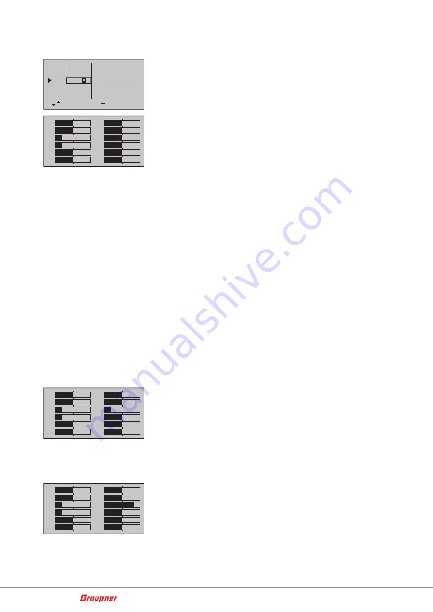
In the servo display this looks like the picture on the left: The bars of
C5 and C7 already end at -100% and the bar of C6 ends in the mid-
dle, at 0%.
When starting in autopilot mode with a throttle position above the
center of the stick (0%), the copter automatically raises to a altitude
of approx. 1m so that it can hold the position.In autopilot mode, an
electronic grid at 500 m distance and the set max. altitude active.
When the limits are reached, a corresponding warning message is
transmitted to the transmitter.
• When starting in autopilot mode, the copter will lift off as soon
as the pitch control stick is pushed past the center position. In
the middle position of the pitch control stick, the height is held;
below the center position, the copter drops accordingly.
• If you start in the Rate or Attitude mode and then switch to the
autopilot mode, the throttle position when switching is the stick
position where the altitude is maintained.
• As soon as the switch S3 is placed in the rear switch position and
the bar of K7 extends beyond the value of +50 % to the right, the
Copter is in the Carefree auto pilot mode. How far to the right of
+50 % is irrelevant.
Come back home
The reference point for this mode is always the position of the cop-
ter at the time when the motor stop switch has been switched to the
ON position.
1
3
5
7
+
0%
–100%
9
11
–100%
0%
2
4
6
8
+
0%
0%
0%
0%
10
12
0%
0%
0%
–100%
As long as the upper right switch S3 is in the front position and both
the left front switch S4 as well as the right front switch S6 are in the
upper switch position, the copter is in the GPS-controlled come back
home mode, as long as the right front switch S6 is held in the upper
switch position.
In the servo display this looks like the picture on the left: The bars of
C5, C6 and C7 already end at -100%.
Flying on preset waypoints
As long as the left front switch S4 is in the upper position, the right
front switch S6 is in the lower position and the upper right switch S3
is in the front switch position, the copter flies GPS previously pro-
grammed waypoints.
In the servo display this looks like shown on the left: The bar of C5
and C7 already ends at -100% and the bar of C6 only on the right, at
+100%.
To create the waypoints you will need:
1
3
5
7
+
0%
9
11
–100%
0%
2
4
6
8
+
0%
0%
0%
0%
10
12
0%
0%
0%
0%
–100%
I5
I6
I7
+
trv
+100% +100%
+100%
+100% +100%
I8
+100% +100%
free
SW6/7
3
SW4/5
+100%
I9
+100% +100%
free
1
3
5
7
+
0%
–100%
9
11
–100%
0%
2
4
6
8
+
0%
0%
0%
0%
10
12
0%
0%
0%
–100%
+100%
Summary of Contents for Alpha 150Q
Page 2: ...2 48 16571 GPS_Alpha150Q_V2 0sh en...
Page 19: ...19 48 16571 GPS_Alpha150Q_V2 0sh en...
Page 21: ...21 48 16571 GPS_Alpha150Q_V2 0sh en Turn yaw Forward and backward nick v...
Page 22: ...22 48 16571 GPS_Alpha150Q_V2 0sh en MODE 2 Climb and sink Turn yaw...
Page 23: ...23 48 16571 GPS_Alpha150Q_V2 0sh en Roll to the right and left Forward and backward nick...
Page 24: ...24 48 16571 GPS_Alpha150Q_V2 0sh en MODE 3 Climb and sink Turn yaw...
Page 25: ...25 48 16571 GPS_Alpha150Q_V2 0sh en Roll to the right and left Forward and backward nick v...
Page 26: ...26 48 16571 GPS_Alpha150Q_V2 0sh en MODE 4 Climb and sink Roll to the right and left...
Page 27: ...27 48 16571 GPS_Alpha150Q_V2 0sh en Turn yaw Forward and backward nick...
Page 43: ...43 48 16571 GPS_Alpha150Q_V2 0sh en...
Page 48: ......


