


Ignite SDC/HDC Robotic Camera Instruction Manual
65
Menu Selections
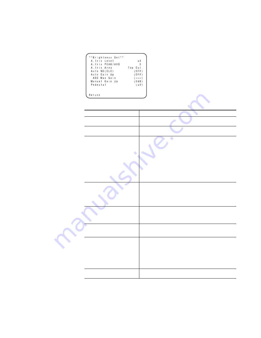
Brightness Setting
Figure 36. Brightness Setting Submenu
Table 19.
Brightness Settings
Selection
Description
Iris Level
(-50 to +50) Convergence level of AUTO IRIS/AUTO GAIN UP/ AUTO ND
(ELC) can be adjusted.
Iris PEAK/AVG
(P50 to A50) The ratio of AUTO IRIS/AUTO GAIN up/AUTO ND (ELC)
detected peak to average can be adjusted within a predetermined range.
Iris Area
A photometric measurement method can be selected for AUTO IRIS/AUTO
GAIN UP/AUTO ND (ELC).
ALL: All the screen area is measured.
Center: The screen is measured mainly in the center area, about
one-third of both the top and bottom and one-third of both the right
and left portions of the screen are excluded from measurement.
Top Cut: About one-third of the top part of the screen is excluded
from measurement.
BTM Cut: About one-third of the bottom portion of the screen is
excluded from measurement.
R/L Cut: About one-third of both the right and left portions of the
screen are excluded from measurement.
Auto ND (ELC)
OFF: Luminance is not automatically adjusted by the electronic shutter.
ON: The electronic shutter is controlled to automatically adjust the lumi-
nance.
*ON is automatically selected when the Shutter Speed on the submenu
[Other Set] is set to [Auto ND].
OFF is selected when other than [Auto ND] is selected.
Auto Gain Up
OFF: The light quantity is not adjusted automatically.
ON: The light quantity is adjusted automatically. The maximum to which
the gain can be increased using the Auto Gain Up function is selected by
the AGC Max Gain setting.
AGC Max Gain
(6dB, 12dB, 18dB, 24dB, N/Eye L, N/Eye H) This is used to set the maxi-
mum amount to which the gain can be increased when “ON” has been
selected as the Auto Gain Up setting.
Manu Gain Up
Manual setting is possible only when the Auto Gain Up setting is “OFF”.
0 dB: 0 dB should be selected in normal cases.
1 dB - 30 dB: Use this range if sufficient video output cannot be obtained
even when the lens iris is opened in shooting dark scenes.
N/Eye L (Night Eye L): Use this mode if sufficient video output can not be
obtained even if 30 dB gain up should be selected.
N/Eye H (Night Eye H): Use this setting if it is not possible to achieve a sat-
isfactory video output even at the Night Eye L setting.
Pedestal
(-150 to +150) The black level (pedestal) of the luminance (Y) signal can
be set. Used in adjusting the black levels of two or more cameras.
8492_28_r0
Summary of Contents for Ignite HDC Series
Page 8: ...8 Ignite SDC HDC Robotic Camera Instruction Manual Contents ...
Page 10: ...10 Ignite SDC HDC Robotic Camera Instruction Manual Preface ...
Page 22: ...22 Ignite SDC HDC Robotic Camera Instruction Manual Section 1 Overview ...
Page 36: ...36 Ignite SDC HDC Robotic Camera Instruction Manual Section 3 Operation ...
Page 40: ...40 Ignite SDC HDC Robotic Camera Instruction Manual Section 4 Service ...
Page 106: ...106 Ignite SDC HDC Robotic Camera Instruction Manual Appendix C HD Camera Block ...
Page 110: ...110 Ignite SDC HDC Robotic Camera Instruction Manual Appendix D Robotic Pan Tilt Head ...
Page 116: ...116 Ignite Glossary Glossary ...


