


7-24
9
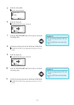
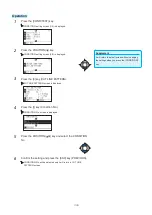
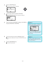
Press the POSITION ( ) keys and increase or decrease the
setting value.
10
Confirm the setting and press the [ESC] key (PREVIOUS).
Tool Interval Adjustment screen is displayed.
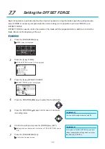
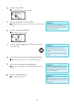
11
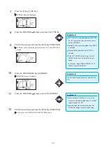
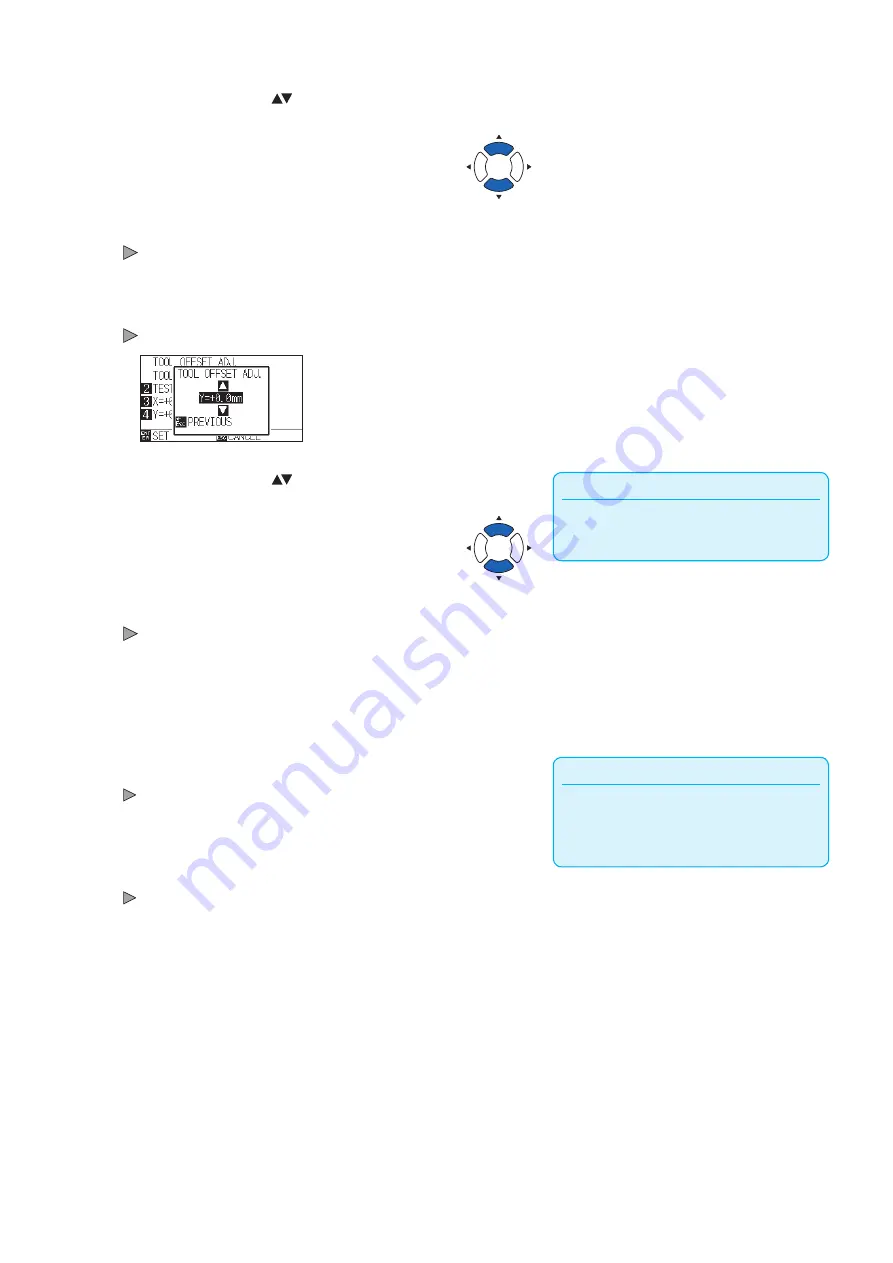
Press the [4] key (Y=+0.0mm).
Tool 1-2 Interval Adjustment (Y) screen is displayed.
Supplement
You can set the range between -3.0 mm and
+3.0 mm.
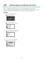
12
Press the POSITION ( ) keys and increase or decrease the
setting value.
13
Confirm the setting and press the [ESC] key (PREVIOUS).
TOOL OFFSET ADJ. screen is displayed.
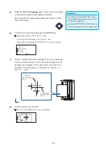
14
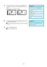
Repeat steps 4 to 13 until the misalignment between the two
tools is corrected.
Supplement
It will return to TOOLS SETTING screen (1/4)
without changing the settings when you press
the [ESC] key (CANCEL).
15
Confirm the interval and press the [ENTER] key (SET).
Setting will be confirmed and it will return to TOOL SETTING (1/4)
screen.
16
Press the [PAUSE/MENU] key.
It will return to default screen.
Summary of Contents for CE7000-130AP
Page 1: ...USER S MANUAL MANUAL NO CE70AP UM 151 CE7000 130AP CUTTING PLOTTER...
Page 2: ......
Page 19: ...1 3 Dedicated accessories A stand with a basket is supplied...
Page 84: ......
Page 104: ......
Page 110: ......
Page 128: ......
Page 184: ......
Page 245: ...A 7 PAUSE MENU 2 Continued MENU screen AXIS SETTING 1 1 Default screen Continued 1 2...
Page 246: ...A 8 3 PAUSE MENU Continued MENU screen AREA PARAMETERS 1 1 Default screen Continued 1 2 3 4...
Page 250: ...A 12 PAUSE MENU Continued MENU screen TEST 1 2 TEST 2 2 Default screen Continued 2 3 1 1 4...
Page 251: ...A 13 PAUSE MENU MENU screen MEM SETTING 1 1 1 Default screen Continued Default screen Finish...
Page 254: ......
Page 258: ......
Page 260: ......


