background image

606-WS

SHORT

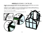
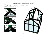
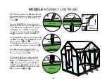
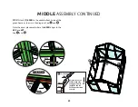
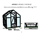
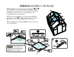
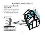
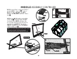
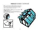
MIDDLE ASSEMBLY CONTINUED

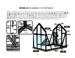
4.11 

Before you attach the 602A’s to the sides 

of the greenhouse you will need to remove the  

ML01 nuts attached to the S03L08C-X. See 

diagram       .  

1. Use the S03/ML01 combos to attach the 

FMZ to the base, and  allow the L08C-X to rest, 

set the 602A onto the S03 bolts attached to 

the FMZ. Be sure the 602A is aligned and 

sitting flush with bottom edge of the BASE

See        for reference. Tighten the ML01 nuts. 

2. Hold the 602A in place and attach the top of 

the 602A to the 609 using S04/ML01 (nut and 

bolt). As shown in        and         . 

* Note 6x4 size greenhouses you will install 

only (1) 602A per side, and it will look like        .

3. For 6x8 sizes repeat steps 1 and 2 on all 

four corners where the L08C-X ‘s meet the 

base, and replace with an FMZ

4. If building a 6x8 size greenhouse attach 

the remaining 602A’s to the FMZ and the 

BASE with the S03/ML01 combo as shown 

in        . Then attach the top of the 602A to 

the 609 with an S04/ML01, be sure to align 

the top of the 602A to the exact line on the 

609 as is shown in         and         .

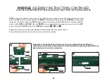
602A

S04/ML01

609

UP

602B

609

Profile View

Groove

602A

Note Exact 

Placement

of 602A and 602B.

41

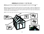
Inside View

L08C-X

S03/ML01

Inside View

FMZ

602A

S03/ML01

Inside View

L08C-X

FMZ

602A

S03/ML01

Inside View

602A

602A

Summary of Contents for Grandio Element 6x4 with Base Kit

Page 1: ...rce Inc All rights reserved February 2 2016 Extendable Models 2016 GRANDIO ELEMENT WITH BASE KIT 6X4 6X8 4 EXTENSION KIT MANUAL Grandio Element 6x8 with Base Kit Shown In Image STOP This manual is for...

Page 2: ...Greenhouse will be covered on your policy Call your local utilities companies before digging Do not attempt to begin construction on a windy day plan to complete assembly in one day Damage caused by i...

Page 3: ...side has a UV coating and we recommend marking a small x on a corner of each panel to determine which side has the UV Coating as you cannot visually determine with your eye in the case of future disa...

Page 4: ...or Assembly 4 Box Configurations 6 Diagrams of Assembled Grandio Sizes 6x4 6x8 6x12 7 9 Base Kit Assembly Information 10 Base Kit Parts Lists 12 6x4 Base Kit 14 6x8 Base Kit 15 6x12 Base Kit 17 Base K...

Page 5: ...and use a permanent marker to place a small X on the lower right corner of each panel on the clear side that faces the sun each panel has a sticker labeling the panel number and this side always face...

Page 6: ...4 mm EAVE HEIGHT 97 1 4 2470 mm BASE 3 1 4 82 6 mm 1 3 4 44 4 mm GUTTERS FRONT 74 1880 mm 6x8 GRANDIO ELEMENT A FRAME STYLE GREENHOUSE WITH DIRT MOUNT BASE KIT DIMENSIONS SEE BASE KIT ASSEMBLY SECTION...

Page 7: ...e items in the grass or dirt near your building site See the reference diagrams on pages 7 9 for more information about how the parts will go together and what makes up each section for the assembly G...

Page 8: ...610 610 618 Y6 Y5 Y4 2 Y4 1 Y12 Y2 2 Y1 Y3 1 Y9 Y8 Outside View 606 WS 606 WS BA S7 L08A X 606 WS SHORT 603B Y7 Y7 Y8 Y8 Y10 606 WS 606 WS Y7 Y7 Y6 Y2 1 Y1 606 WS 606 WS 606 WS Y12 Y12 DIAGRAM SHOWS T...

Page 9: ...610 618 L08C X 618 L08A Y6 Y5 Y4 2 Y4 1 Y12 Y2 2 Y1 Y3 1 Y9 Y9 Y7 Y8 Outside View 606 WS 606 WS 606 WS 606 WS BA S7 L08A X 606 WS SHORT 603B Y7 Y7 Y7 Y8 Y8 Y8 Y8 Y8 Y10 Y10 BA S2 BA S2 606 WS 606 WS...

Page 10: ...Y7 Y8 Outside View 606 WS 606 WS 606 WS 606 WS L08A X 606 WS SHORT 603B Y7 Y7 Y7 Y8 Y8 Y8 Y8 Y8 Y10 Y10 606 WS 606 WS 606 WS 606 WS Y7 Y7 Y7 Y7 Y6 Y2 1 Y1 606 WS 606 WS 606 WS Y12 Y12 602D 603B 603C...

Page 11: ...ase is level and square be sure all panels are tightly in place and that all aluminum extrusions are tight The main problem is usually that wind gets into the greenhouse and the pressure pushes a pane...

Page 12: ...HARDWARE TO SECURE YOUR DIRT MOUNT BASE KIT TO YOUR SURFACE IF YOU ARE INSTALLING INTO AN EARTH SURFACE USE THE GRANDIO BASE KIT WITH THE BA A1 L BOLT ANCHORS YOU MAY ALSO MOUNT THE DIRT MOUNT BASE K...

Page 13: ...80 mm 74 6x4 1206 mm 47 1 2 6x8 2394 mm 94 1 4 138 mm 5 7 16 M6 14 NUT FRAME TO BASE BRACKET M6 10 FLAT MOUNT BASE BRACKET GRA BAS 64 GRA BAS 68 BASE AND ACCESSORY PACKING LIST 2 2 0 4 28 28 9 28 10 2...

Page 14: ...13 IMAGE SHOWS A 6 x 8 DIRT MOUNT BASE KIT WITH L BOLT ANCHORS FOR EARTH INSTALLATION 6x8 BASE KIT ASSEMBLED WITH ANCHORS GRA BAS 68 BACK LEFT RIGHT FRONT...

Page 15: ...E ARE 8 HOLES IN THE BOTTOM OF THE BASE FOR ANCHORS 6x4 BASE KIT ASSEMBLY INSTRUCTIONS GRA BAS 64 BA S8 BA S8 1 1 Layout all base kit pieces to prepare for assembly of a 6x4 Note that one BA S7 will b...

Page 16: ...r the 6x8 Element kit you will have BA S2 s on both sides See 15 74 1880 mm 97 1 16 2465 mm HOLE FOR ANCHOR HOLE FOR ANCHOR HOLE FOR ANCHOR HOLE FOR ANCHOR 6x8 BASE KIT ASSEMBLY INSTRUCTIONS GRA BAS 6...

Page 17: ...ill be at front and the back while the BA S2 s or BA S8 will be the sides of your greenhouse base 1 4 Locate the anchoring devices for your installation needs and follow the directions for that anchor...

Page 18: ...the front and one BA S7 will be at the back and the BA S2 s will be on the sides attaching to the front BA S1 The BA S5 and BA S6 will attach to the back BA S7 See diagram 1 6 Attach the BA S2 to the...

Page 19: ...S6 accordingly 1 8 For Ground Installation only Insert the BA S03 and the BA A1 into the holes at the bottom side of the corners of the base the nut will be tightened on the inside of base see and Lo...

Page 20: ...ions on the package See www GrandioGreenhouses com for other anchoring kit options BASE KIT GROUND INSTALLATION BA S2 BA A1 BA S7 BA S03 BA A1 Must be inserted into the ground and secured with concret...

Page 21: ...e fastener to attach to your surface through these access holes BA C4 BA S6 BA S2 BA S03 BA M03 BA S1 BA C3 BA S2 HOLE FOR ANCHOR BOLT OR SCREW BASE KIT DECK INSTALLATION BASE MUST BE LEVEL SQUARE FOU...

Page 22: ...e all nuts and bolts pre thread and place in the groove of the extrusion to make installation easier Move up or down for exact placement FRONT FRAME ASSEMBLY ALWAYS ASSEMBLE FRONT HORIZONTAL This pict...

Page 23: ...W02 W02 W08 FAT END FAT END Fat End on the W02 s will always face downward Transparent Clear Film Opal White Film Polycarbonate Panels Sun The UV Protected side is covered with clear film and must fac...

Page 24: ...vents bolt from falling into the track GRANDIO T I P BOLT INSTALLATION TIP Locate all nuts and bolts pre thread and place in the groove of the extrusion to make installation easier Move up or down for...

Page 25: ...s and 604 s using S04 ML01 fasteners make sure it is snug with the tops of the Y1 panels then tighten fasteners See and 2 10 Insert the Y2 2 and Y2 1 polycarbonate panels into the track of the 603B S...

Page 26: ...1 603B L08D L08D 604 L 604 R 601A 601A 606 WS SHORT 606 WS SHORT 619 603B 2 11 Move roof and lower front section together and align the W02 s into the 601A s and align the S04 ML01 s on the W02 T s in...

Page 27: ...hes up from 619 see GRANDIO T I P Set front aside in a shaded area do not lay on grass prolonged sunlight through the polycarbon ate panels will burn if placed directly on top of plants during the int...

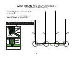
Page 28: ...O T I P Transparent Clear Film Outside Greenhouse Opal White Film Inside Greenhouse Polycarbonate Panel Sun BACK ASSEMBLY INSTRUCTIONS ALWAYS ASSEMBLE BACK HORIZONTAL This image shows the inside view...

Page 29: ...into 2 601B s then tighten S05 screws as shown in diagram Note the fat end of the W02 s will always be on the bottom side BACK CONTINUED ALWAYS ASSEMBLE BACK HORIZONTAL IMPORTANT Use only S05 Screws o...

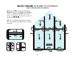
Page 30: ...g the S03 ML01 See diagram TIP If necessary you may use a screwdriver to wedge behind the bolt head This prevents bolt from falling into the track BACK FRAME ASSEMBLY CONTINUED ALWAYS ASSEMBLE FRONT H...

Page 31: ...Y12 panels are inserted into 606 WS as shown in You may need to use a screwdriver to gently open the 606 WS to fit the polycarbonate panels into the groove of 606 WS 3 8 Set the 3 603C s atop each of...

Page 32: ...outward See diagrams 3 10 Insert the Y5 polycarbonate panel into place Then insert the Y4 1 and Y4 2 into place as shown in the diagram 601A 602D 603C L08B Y12 S04 ML01 L08B 601A 602D L08B 603C 603C 3...

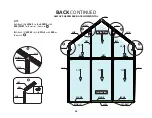
Page 33: ...shown in B Attach 2 W02 s to 2 601A s with S05 as shown in BACK CONTINUED ALWAYS ASSEMBLE BACK HORIZONTAL S05 W02 601B 601A 32 Y5 Y4 2 Y4 1 Y12 Y12 Y12 Inside View 603C L08A 602D 602D 601A 601A 606 W...

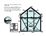
Page 34: ...or use a measuring tape to make sure corner measurements are the same tighten L08A X s to hold squareness L08A X should be attached a few inches up from L08A see 602D 602D 601A 601A 606 WS 606 WS 606...

Page 35: ...until the L08C X angle supports are attached securely to the front and back wall and sides of the base kit as shown in step 4 3 Failure to hold front or back wall vertical will cause them to fall and...

Page 36: ...e holes where the S06 screws will attach the DP01 to the 607 ridge See Immediately align the DP01 apply a small amount of silicone to the holes on the exterior of DP01 then insert the S06 screws NOTE...

Page 37: ...correct side faces down see 4 4 Locate the 2 609 4X s align each with the 609 and 609 XS brackets Make sure that no notches are right next to each other If the 609 pieces are matching up correctly ma...

Page 38: ...ombos are tight 4 7 Use 2 of the W05 clips to attach the backwall where the 601A s meet the corner of the base as shown in and 2 W05 clips where 602D s meet the BA S7 see You will switch out the S03 M...

Page 39: ...s and the 604 s you will switch out the S03 ML01 combos that were originally used for the 601A s and 604 s over to the W05 Clip Combo If building a 6x8 you will have 4 L08C X s to attach for support b...

Page 40: ...f building a 6x4 Greenhouse Person 1 will need to hold the front wall upright and steady and hold the end of the 609 while Person 2 attaches the 609 2 Repeat step 1 for the other end of 609 3 With one...

Page 41: ...and back by sliding into place as shown in and using S04 ML01 fasteners attach the 607 to the 601B s See for how the final orientation should be MIDDLE ASSEMBLY CONTINUED 601B 601B 607 607 601B 601B...

Page 42: ...and bolt As shown in and Note 6x4 size greenhouses you will install only 1 602A per side and it will look like 3 For 6x8 sizes repeat steps 1 and 2 on all four corners where the L08C X s meet the base...

Page 43: ...when installed correctly MIDDLE ASSEMBLY CONTINUED 4 12 Attach 1 602B to the middle of each side of the greenhouse as shown in the diagram See and Note the exact placement where the 602B aligns to th...

Page 44: ...pport to the inside of the 619 with 3 S19 self tapping screws included in the package see BA S7 604 601A 601A 619 Attaches to the base kit with S04 ML01 619 BAR will attach 619 BAR will attach to the...

Page 45: ...ow into the end of ridge of 607 and slide into position See Window positions are your discretion a 6x4 will have 1 roof vent and a 6x8 will have 2 roof vents 4 16 For a 6x8 attach the additonal 602B s...

Page 46: ...WS before inserting polycarbonate sheet Y7 s see Install all Y7 panels into the channel s of the side walls and fit down into the 606 WS 4 18 After Y7 s are installed loosen bolts attached to L08C X i...

Page 47: ...oles of the handle to the second and third pins of HQC02 Then attach HQC02 into 603C s track with S04 ML01 nuts and bolts see 603B 618 616 616 603B 616 Z04 HQC02 Y10 Y10 HQC01 Handle Note If you are i...

Page 48: ...shown in the diagram once the panels are in place 4 22 Slide 610 Gutters into 609 s groove as shown in the diagrams and Repeat on both sides FOR EXTENSION KIT Note the orientation of the gutters the...

Page 49: ...the screws install the S07 screws through the DP02 and into the DP02B See diagram and Repeat these steps to assemble the additional set s for both sides of your greenhouse Remove the tape from the pa...

Page 50: ...rubberized silicone or construction adhesive into the ends of ridge to secure pressure fit end caps You will need to quickly secure the Z03 s into the J602A E and J602B E It is recommended to caulk an...

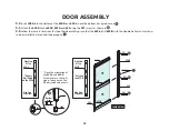
Page 51: ...623A J08A J08A 622 R UP UP Side View 622 J08A Bottom View Inside View DOOR ASSEMBLY DIAGRAM This image shows the inside view of Right Door Assembly All parts for door assembly will be found in box GR...

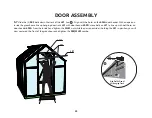
Page 52: ...he wrong way Be careful not to strip the phillips heads when assembling 5 1 Insert J08A s into the bottom of the 622 s note the bottom groove is smaller than the top groove of 622 see 5 2 Use the Z01...

Page 53: ...rews as shown in 5 6 Follow the same instructions for the other door making sure that the 622 L and 622 R with the double ball catch match up so doors will latch closed and slide properly Y6 Y6 623B 6...

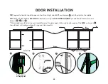
Page 54: ...g door track L21 with door header 603D move bolts on L21 to line up with bolt holes on door header 603A From the inside hand tighten the ML01 nut while the person outside is holding the L21 in positio...

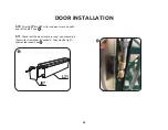
Page 55: ...HNDL NUT BOLT provided to both doors as shown below in and We included some felt dots in your Grandio Welcome Kit please apply to the inside bottom edge of the 623B as shown in these felt dots will ma...

Page 56: ...N J07 5 10 Attach J07 s to L21 with included screws on both ends of the L21 See 5 11 Check that the door locks are snug you may adjust them with screwdriver if needed as they may be tight ened or loos...

Page 57: ...ickers to make your greenhouse shine FINAL SUPPORT INSTALLATION 5 12 Attach the 2 L08C s along the inner roof as shown in the image The L08C s will attach to the 601A s and the 602B s with S04 ML01 co...

Page 58: ...AT MOUNT BASE BRACKET M6 10 1206 mm 47 1 2 2394mm 94 1 4 1206 mm 47 1 2 2394mm 94 1 4 1206 mm 47 5 8 2397mm 94 3 8 578 mm 22 3 4 ROOF VENT 578 mm 22 3 4 ROOF VENT 500 mm 19 3 4 ROOF VENT 1800 mm 70 7...

Page 59: ...3 W16 HQC01 HQC02 Z04 S04 ML01 Z02 S10 W02 T END CAPS END CAPS END CAP 34 MM PLUG FOR ROOF VENT SCREW DRIVER 10 MM NUT DRIVER 10 MM WRENCH ROOF VENT ARM ROOF VENT LATCH ROOF VENT HARDWARE M3 5 16 Scre...

Page 60: ...J07 622 622 R 622 L 623A 623B J08A GRAPHIC PART NAME SIZE LOCATION QTY 64A 68A 4 4 SETS 2 1 2 SETS 2 1 1 2 2 4 DOOR HANDLES 4 FASTENER SETS 330 mm 13 1500 mm 59 1 16 L21 END CAP 2 SCREWS 1772 mm 69 3...

Page 61: ...IGHT 2 6x4 QTY 6x8 QTY 2 1 1 1 1 1 1 2 4 3 1 1 3 488 mm 19 3 16 488 mm 19 3 16 488 mm 19 3 16 775 mm 30 1 2 578 mm 22 3 4 578 mm 22 3 4 578 mm 22 3 4 360 mm 14 3 16 578 mm 22 3 4 578 mm 22 3 4 578 mm...

Page 62: ...1 4 SIDEWALL SUPPORT GRAPHIC PART NAME SIZE LOCATION QUANTITY 4 4 1 2 1 1 5 3 1 2 606 WS 609 4X R 609 4X L 609 XS S09 610 4X R 610 4X L DP02 DP02B S07 615 616 618 553mm 21 3 4 WINDOW SEAL 1187 mm 46...

Page 63: ...VENT M3 5 16 SCREWS FOR ROOF VENTS ROOF VENT ARM ROOF VENT LATCH HQC01 HARDWARE M6 10 FLAT MOUNT BRACKETS 100 mm 4 50 2 5 1 1 2 EACH 5 4 4 GRAPHIC PART NAME SIZE LOCATION QUANTITY GRA ELE 4XA GRANDIO...

Page 64: ...ROOF VENT PANEL GRAPHIC PART SIZE LOCATION WIDTH HEIGHT 1 HEIGHT 2 QTY 4 3 1 1 578 mm 22 3 4 578 mm 22 3 4 578 mm 22 3 4 578 mm 22 3 4 1450 mm 57 1 16 1109 mm 53 5 8 486 mm 19 1 8 570 mm 22 7 16 GRA E...

Page 65: ...R ROOF VENT PANEL GRAPHIC PART SIZE LOCATION WIDTH HEIGHT 1 HEIGHT 2 QTY 4 3 1 1 578 mm 22 3 4 578 mm 22 3 4 578 mm 22 3 4 578 mm 22 3 4 1450 mm 57 1 16 1109 mm 53 5 8 486 mm 19 1 8 570 mm 22 7 16 GRA...

Page 66: ...related expenses for removal installation or replacement of the greenhouse or its components are not covered under this warranty 4 This warranty does not cover scratching or scuffing of the product t...

Page 67: ...NOTES NOTES...
Page 68: ...SAFE PLACE FOR REFERENCE CONTACT US IF YOU NEED HELP OR HAVE MISSING OR DAMAGED PARTS GRANDIOGREENHOUSES COM BACKYARD LIVING SOURCE INC 9543 W EMERALD ST SUITE 101 BOISE ID 83704 1 866 448 8231 2015...

Reviews: