17
BA-S2
BA-S7
BA-S2
BA-C3
BA-C3
BA-C3
BA-C4
BA-S5
BA-S6
HOLE FOR
ANCHOR
BA-C4
BA-S10
BA-S10
GRANDIO
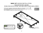
T I P
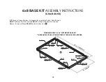
Note that the holes for
screws on the base kit
sides have about a 2 foot gap between
each, so be sure base kit extensions
are assembled properly. See .
237
5/8
” / 6036 mm
HOLE FOR
ANCHOR
HOLE FOR
ANCHOR
HOLE FOR
ANCHOR
HOLE FOR
ANCHOR
74
” 1880 mm
1.5
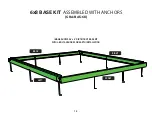
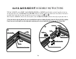
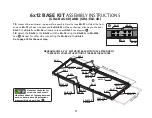
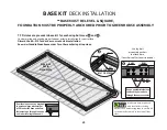
Layout all base kit pieces to prepare for assembly. Note that one BA-S7 will be at the front
and one BA-S7 will be at the back and the BA-S2’s will be on the sides attaching to the front
BA-S1. The BA-S5 and BA-S6 will attach to the back BA-S7, See diagram .
1.6
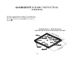
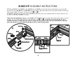
Attach the BA-S2 to the BA-S5 with the BA-C4 using the BA-S03 and BA-M03.
See . Repeat for other side connecting the BA-S6 and the BA-S2.
Go to page 18 for the next step.
6x12 BASE KIT ASSEMBLY INSTRUCTIONS
(GRA-BAS-68) AND (GRA-ELE-4X)
BA-C4
BA-S5
BA-S2
BA-S03
BA-M03
HOLE FOR
ANCHOR
BA-S7
HOLE FOR
ANCHOR
HOLE FOR
ANCHOR
HOLE FOR
ANCHOR
BA-C3
DIAGRAM SHOWS A 6’ x 8’ DIRT MOUNT BASE KIT WITH A 4’ EXTENSION KIT
*THERE ARE 12 HOLES IN THE BOTTOM OF THE BASE FOR ANCHORS
Summary of Contents for Grandio Element 6x4 with Base Kit
Page 67: ...NOTES NOTES...

