46
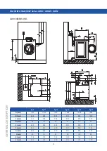
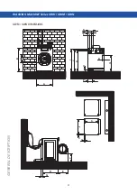
WASHING MACHINE Series GWH / GWM / GWN
INST
ALLA
TION, CONNECTIONS, AND ADJUSTMENTS
SECURING
To
secure
the appliance, perform the operations described below.
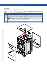
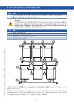
After locating the appliance in the place of installation, proceed to
remove the appliance upper, front, rear, central and lower
panels
(the latter only in some models where fixings are less accessible):
Step
Action
1
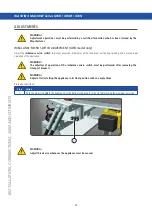
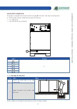
Unscrew the two M6 Torx head rear screws to remove the top panel.
2
Remove the front service panel (secured with two M6 torx head screws on the bottom and 2 M4 torx head screws on
the top).
Note:
Pay attention to the electrical connection of the emergency stop button.
3
Unscrew the M6 Torx head screws to remove the central rear panel and the lower rear panel (the latter in models where
fixing holes are less accessible).
4
Remove the rear panel of the switchboard where electrical connections will be made;
Summary of Contents for GWH Series
Page 9: ...9 IDENTIFICATION DECLARATION OF CONFORMITY copy ...
Page 81: ...81 TROUBLESHOOTING ...
Page 82: ......

