55
INST
ALLA
TION, CONNECTIONS, AND ADJUSTMENTS
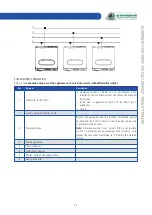
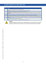
POWER SUPPLY CONNECTION
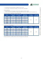
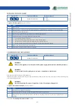
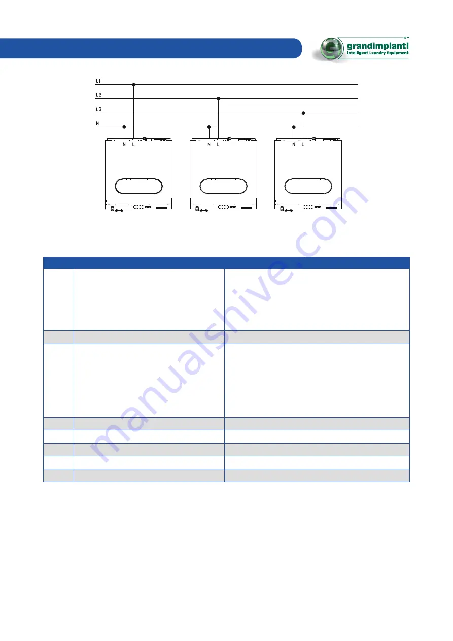
Below is the
connection diagram of the appliance to the electrical mains (with differential switch)
:
Pos.
Element
Description
1
Differential switch (RCD)
• Operating current = 100mA (if it is not allowed in the
installation site, use 30mA current, and choose the minimum
delay type).
• Install max. 2 appliances for each RCD (for 30mA just 1
appliance).
• Type B.
2
Laundry power distribution board
3
Power protection
Protects the equipment and the electrical installation against
overload and short circuit. Fuses or circuit breakers can be used
as power protection devices.
Note:
Protection must be "slow", curve D. If this is not possible,
use the 1st protective device exceeding rated current so as to
prevent the connection from being cut off during the machine
start-up.
4
Washing machine
5
Phase conductors
6
Protective conductor
7
Master switch power supply clamp
8
Neutral conductor
Summary of Contents for GWH Series
Page 9: ...9 IDENTIFICATION DECLARATION OF CONFORMITY copy ...
Page 81: ...81 TROUBLESHOOTING ...
Page 82: ......

