background image

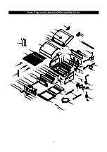
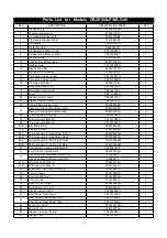
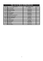
Parts List for Models OB3210ALP/NG & OB3210BLP/NG-Grill

10

KEY

DESCRIPTION

OB3210ALP/NG PART# OB3210BLP/NG PART#

QTY

1

Lid Ass embly

P0014734AA

P0014734AA

1

2

Temperature Gauge

P00601381A

P00601381A

1

3

Lid Handle Bracket, Left

P00307058E

P00307058E

1

4

Lid Handle Bracket, Right

P00308058E

P00308058E

1

5

Lid Handle

P00215036H

P00215036H

1

6

Protective Pad

P05518002I

P05518002I

4

7

Lid Ass embly Bracket, Left

P03320007C

P03320007C

1

8

Lid Ass embly Bracket, Right

P03320008C

P03320008C

1

9

Lid Trim Plate

P0014735QJ

P0014735QJ

1

10

Cooking Rack/Secondary

P015160282

P015160282

1

11

Cooking Grid

P01615038H

P01615038H

5

12

Electric Wire Set

P02627014A

P02627014A

1

13

Electric Wire Protector

P055330043

P055330043

1

14

Connection Hose - Long

P03702037D

P03702037D

2

15

Connection Hose - Short

P03702038D

P03702038D

2

16

Lid Hinge with Nut

P05501136L

P05501136L

2

17

Bowl Side Panel, Left

P0076113EC

P0076113EC

1

18

Bowl Side Panel, Right

P0076213EC

P0076213EC

1

19

Bowl

P0071388EC

P0071388EC

1

20

Grease Shield, Upper

P06902131C

P06902131C

2

21

Grease Shield, Lower

P06902132C

P06902132C

2

22

Infrared Burner Assembly

P02005027B

P02005027B

4

Extension Fitting with Orifice (LPG)

P06539032A

P06539032A

4

Extension Fitting with Orifice (NG)

P06539033A

P06539033A

4

24

Cros s Lighting Channel

P02212377A

P02212377A

2

25

Thermocouple Protector

P03343017C

P03343017C

4

26

Thermocouple Bracket

P03327082C

P03327082C

2

27

Thermocouple Bracket

P03327083C

P03327083C

2

28A

Electrode, Front

P02618056A

P02618056A

2

28B

Electrode, Rear

P02618057A

P02618057A

2

29A

Thermocouple for Gas Valve

P05305054B

P05305054B

2

29B

Thermocouple for Gas Valve

P05305055B

P05305055B

2

30A

Thermocouple for LED Light, Left Front

P05305056B

P05305056B

1

30B

Thermocouple for LED Light, Left Rear

P05305057B

P05305057B

1

30C

Thermocouple for LED Light

P05305058B

P05305058B

1

30D

Thermocouple for LED Light

P05305059B

P05305059B

1

31

Control Panel Heat Shield Bracket

P0300616FD

P0300616FD

1

32

Control Panel Heat Shield

P06904056C

P06904056C

1

Gas  Valve/Manifold Ass embly (LPG)

Y0060679

Y0060679

1

Gas  Valve/Manifold Ass embly (NG)

Y0060680

Y0060680

1

34A

LED Light with Wire - A

P02615155A

P02615155A

1

34B

LED Light with Wire - B

P02615156A

P02615156A

1

34C

LED Light with Wire - C

P02615157A

P02615157A

1

34D

LED Light with Wire - D

P02615158A

P02615158A

1

35

Bowl Front Trim Plate Assembly

P02915341S

P02915341S

1

36

Control Panel

P02915553X

P02915553X

1

37

Control Knob Seat

P03439014A

P03439014A

4

38

Control Knob

P03436053V

P03436053V

4

39

Switch for LED Light

P05360001B

P05360001B

1

40

Switch Cover for Light

P05382004P

P05382004P

1

41

Electric Ignitor, 4-Port

P02502384C

P02502384C

1

42

Bowl Panel, Rear/Lower

P0073740BC

P0073740BC

1

Bowl Panel, Rear/Upper (LPG)

P0073741BC

P0073741BC

1

Bowl Panel, Rear/Upper (NG)

P0073742BC

P0073742BC

1

44

Lamp,12V, 10W

P05352012B

P05352012B

2

45

Lamp Wire Set

P05352014B

P05352014B

1

46

Lamp Cover

P05352013E

P05352013E

2

23

33

43

Summary of Contents for OB2610ALP

Page 1: ...and live electrical appli ances THISGASAPPLIANCEISDESIGNEDFOROUT DOORUSEONLY Never use your gas grill in a garage porch shed breezeway or any other enclosed area Never obstruct the flow of ventilation air around your gas grill housing Never disconnect the gas regulator or any gas fitting while your grill is lit A lit grill can ignite leaking gas and cause a fire or explosion which could result in ...

Page 2: ...ected for use shall not be stored in the vicinity of this or any other appliance 1 2 WARNING DANGER 1 2 3 4 If you smell gas Shut off gas to the appliance Extinguish any open flame Open lid If odor continues keep away from the appliance and immediately call your gas supplier or your fire depart ment WARNING LPG models must be used with Liquid Propane Gas and the regulator assembly supplied Natu ra...

Page 3: ...are and Part Diagrams to ensure all items are included and free of damage Do not assemble or operate the grill if it appears dam aged If there are damaged or missing parts when you unpack the shipping box or you have questions during the assembly process call 1 877 934 7455 M F 8AM 4 30PM CST for assistance Phillips Head screwdriver US Patented No 7 475 632 European Patent No 1886606 Australia Pat...

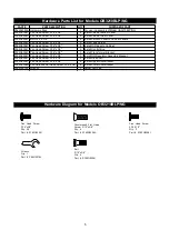
Page 4: ...rdware Pack 1 For use in assembly of Model OB3210ALP OB2610ALP OB3210ANG OB2610ANG S182G03061 Pan Head Screw 3 16 x 3 8 2 Install the Control Box S182G03061 Pan Head Screw 3 16 x 3 8 2 Install the Transformer Bracket S182G03061 Pan Head Screw 3 16 x 3 8 2 Install the Bracket with LP Regulator Model OB3210ALP OB2610ALP Only S182G03061 Pan Head Screw 3 16 x 3 8 3 Install the Tank Tray Set onto the B...

Page 5: ...ottom Panel S182G03061 Pan Head Screw 3 16 x3 8 2 Install Cabinet Rear Panel S185G03061 Bolt 3 16 x3 8 6 Install Partition Panel to Cabinet Panels S182G03061 Pan Head Screw 3 16 x3 8 3 Install Tank Holder S182G03061 Pan Head Screw 3 16 x3 8 8 Install Grill Bowl to Cabinet S182G03061 Pan Head Screw 3 16 x3 8 2 Install Control Box S182G03061 Pan Head Screw 3 16 x3 8 2 Install Transformer Bracket S18...

Page 6: ...els OB2610ALP NG Grill 6 52 1 2 3 5 6 9 10 11 19 4 7 8 6 12 14 15 13 17 16 16 18 21 20 22 34 30 31 32 35 38 39 20 21 22 23 23 24 24 25 26 27A 27B 28B 28A 29B 29A 33A 33B 36 37 40 41 42 61 43 44 45 46 47 48 49 50 51 53 54 63 ...

Page 7: ...031A 2 24 Thermocouple Protector P03343023C 2 25 Thermocouple Bracket P03327082C 1 26 Thermocouple Bracket P03327083C 1 27A Electrode Front P02618058A 1 27B Electrode Rear P02618059A 1 28A Thermocouple for Gas Valve Front P05305055B 1 28B Thermocouple for Gas Valve Rear P05305061B 1 29A Thermocouple for LED Light Front P05305066B 1 29B Thermocouple for LED Light Rear P05305065B 1 30 Control Panel ...

Page 8: ...Controller P05357021B 1 53 Control Box Bracket P03343022C 1 54 Hose 12 FT NG P03703001A 1 55 Regulator Hose Connector LPG P03901046D 1 56 Regulator with Hose LPG P03603049A 1 57A Regulator with Hose NG Y0080039 1 57B Regulator Bracket NG P033110415 1 58 Transformer P05374015B 1 59 Transformer Bracket P03328057A 1 60 Tank Tray Set LPG Y0340050 1 61 Trim Panel Rear P07515025R 1 62 Lighting Stick P05...

Page 9: ...ill 9 60B 39 40 41 44 44 46 46 50 52 53 61 62 64 45 58 34D 34C 21 43 63 59 42 9 7 3 2 5 12 13 14 15 4 6 8 17 16 60A 65 18 38 37 36 34A 35 34B 33 32 31 20 57 47 23 22 30C 28A 25 28B 30D 24 27 30B 19 30A 29B 28B 26 29A 28A 1 21 6 10 11 48 51 55 54 56 49 20 ...

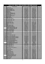
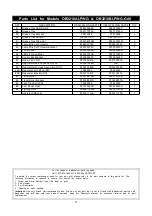
Page 10: ...ocouple Bracket P03327082C P03327082C 2 27 Thermocouple Bracket P03327083C P03327083C 2 28A Electrode Front P02618056A P02618056A 2 28B Electrode Rear P02618057A P02618057A 2 29A Thermocouple for Gas Valve P05305054B P05305054B 2 29B Thermocouple for Gas Valve P05305055B P05305055B 2 30A Thermocouple for LED Light Left Front P05305056B P05305056B 1 30B Thermocouple for LED Light Left Rear P0530505...

Page 11: ...y Heat Shield P06903069C P06903069C 1 48 Grease Tray P02717793C P02717793C 1 49 Grease Tray Bracket Y0270026 Y0270026 1 50 Grease Tray Handle P0272011CC P0272011CC 1 51 Grease Tray Slide Set P05516140M P05516140M 2 52 Lamp Wire Set Protector P055330103 P055330103 2 53 Lamp Wire Set Protector Bracket P03328079C P03328079C 1 54 Control Box P05545006M P05545006M 1 55 LED Light Controller P05357022B P...

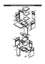
Page 12: ...Parts Diagram for Models OB3210BLP NG Cabinet 12 1A 2A 3A 12 12 11 9 8A 9 7A 6 4A 5 14A 13A 1B 2B 4B 13B 14B 6 10 3B 15 12 12 8B 5 7B 9 17 19 20 21 21 ...

Page 13: ... P01106052B 1 2A Side Shelf Trim Plate Right P07503028A 1 2B Side Shelf Trim Plate Left P07503023A 1 3A Right Cabinet Panel Left P07617050B 1 3B Left Cabinet Panel Right P07618050B 1 4A Right Cabinet Panel Right P07618051B 1 4B Left Cabinet Panel Left P07617051B 1 5 Folding Bracket A P03303147D 2 6 Folding Bracket B P03303148D 2 7A Bottom Panel Right P01001093D 1 7B Bottom Panel Left P01001095D 1 ...

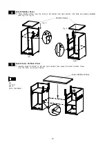
Page 14: ...l Left Right Bottom Panel Install Left Bottom Panel onto left cabinet using 2 Pan Head Screws 3 16 X3 8 and tighten securely as shown below Repeat the step for right cabinet 3 Pan Head Screw 3 16 x3 8 Qty 4 Part S182G03061 Pan Head Screw 3 16 x3 8 Qty 2 Part S182G03061 Install Left Right Rear Panel Place the Left Rear Panel over the installed bolt of the left cabinet see Fig 1 Secure the Left Rear...

Page 15: ...et the bolts are already installed see Fig 3 Fig 4 Fig 3 Fig 4 Partition Panel Bolt 3 16 x3 8 Qty 6 Part S185G03061 Install Outer Partition Panel Install 6 Bolts 3 16 x3 8 to left and right cabinet then place the Outer Partition Panel over the bolts as shown below 5 Left Right Outer Partition Panel ...

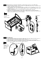
Page 16: ...onto the Left Bottom Panel using 3 Pan Head Screws 3 16 x3 8 and tighten securely only for LP model Pan Head Screw 3 16 x3 8 Qty 8 Part S182G03061 16 Pan Head Screw 3 16 x3 8 Qty 3 Part S182G03061 only for LP model Tank Holder Control Box Support Brackets x4 only for LP Model 7 1 Install Transformer Bracket onto the Right Cabinet Partition Panel refer to step 8 7 Install Transformer Bracket onto t...

Page 17: ...trol Panel to turn on the Grill lamps Install Batteries Place 1 AA battery into the slot of the Control Panel and 4 AAA batteries into the slot of the Control Box as show below Position the caps onto the slots and tighten securely Note The positive pole of the AA battery must face towards the cap For the AAA batteries 2 batteries must have the positive pole facing towards the cap and 2 batteries m...

Page 18: ... Hose Connector and Install LP Regulator only for OB3210BLP Model 9A Make sure the slot is aligned with the screws Pan Head Screw 3 16 x1 2 Qty 2 Part S182G03081 Install Cabinet Right Left Side Shelf 10 Place the Right Side Shelf over the bolts on the Cabinet Rear Panel Then slide the Right Side Shelf from the back to the front Secure the Right Side Shelf to Grill Bowl Right Panel using 1 Pan Head...

Page 19: ...h each other use the wrench to adjust the level adjusters on the bottom of the cabinet side panels see Fig 3 Turn the adjusters clockwise to raise the height of the Grill Turn the adjusters counterclockwise to lower the height of the Grill FOR YOUR SAFETY DO NOT TILT your Grill at any time Match the Door Upper hole to the Upper Door Bracket shaft see Fig 4 Slide or press the spring on the bottom o...

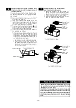
Page 20: ...wl Panel onto the back of the Grill Bowl using the same screws and tighten securely see Fig 2 do not reinstall the Rear Trim panel Fig 1 Fig 2 Rear Trim Panel Rear Lower Bowl Panel Rear Lower Bowl Panel Pull out the Grease Tray Bracket Place the Grease Tray into the Grease Tray Bracket as show below Push the Grease Tray Bracket back into position 12B Grease Tray Grease Tray Bracket Grease Tray 20 ...

Page 21: ...in and have assistant watch for a blue spark within each Ignition Electrode If no spark is seen the Spark Gap needs to be adjusted as follows 13 If the gap between the Spark Electrode Tip and Receiver is more than 1 8 wide use needle nose pliers to gently squeeze the Electrode to narrow gap Try the Electrode Check again If no clicking sound is heard AA Battery may be installed backwards Electric w...

Page 22: ... x3 8 Qty 2 Part S182G03061 Set Grill Head into the Island Install Control Box and Batteries 1 Raise the Grill Bowl and put the Control Box into the inside of the Island then set Grill Bowl into the Island the Island not included as shown below Open your Island Door align the Control Box onto the right underside of the Grill Head as show below Install 2 Pan Head Screws 3 16 x3 8 and tighten secure...

Page 23: ...2 Pan Head Screws 3 16 x3 8 and tighten securely see Fig 1 Install Transformer onto the Transformer Bracket by putting the four pre assembled screws on the Transformer into the four holes on the Transformer Bracket Press the Transformer downward until it rests in place see Fig 2 Install the Transformer Plug into the Transformer Socket and tighten securely See Fig 4 Depending on your island constru...

Page 24: ...e and the ground 4 Install the Partition Panel onto the left island Make sure there is 22 23 inches of clearance between the partition panel and the Tank Tray Set Note The reason we install partition panel is that the Left Island Bottom only allows the usage of 20 pounds gas tank 5 Install Partition Panel for LP Model no included this unit 24 CAUTION Make sure that the space around the gas tank is...

Page 25: ...und is heard AA Battery may be installed backwards Electric wires may be loose Remove the AA Battery and inspect the Ignitor Junction Box found in the Control Box and recon nect any loose wires Spark Electrode Tip Spark Receiver Spark Gap 1 8 Install Grease Tray Heat Shield and Cooking Components 7 Install the Grease Tray Heat Shield by placing the 4 pins on the Grease Tray Heat Shield into the 4 ...

Page 26: ...f the unit Use of alcohol prescription or non prescription drugs can impair your ability to properly assemble and safely operate your grill Keep fire extinguisher readily accessible In the event of a oil grease fire do not attempt to extinguish with water Use type B extinguisher or smother with dirt sand or baking soda In the event of rain turn off the burners and gas supply Wait for the grill to ...

Page 27: ...in construction The top of the upper ventilations open ings must be located within 5 from the top of the built in The bottom of the lower ventilation openings must be at least 1 or less from the floor of the built in The top of the lower ventilation openings cannot be more than 5 from the floor of the built in Every ventilation opening must have a minimum of 1 8 See Step 6 on page 24 Contact a Gra...

Page 28: ...for gas leaks do not smoke Do not use an open flame to check for gas leaks Your grill must be leak tested outdoors in a well venti lated area away from ignition sources such as gas fired or electrical appliances During the leak test keep your grill away from open flames or sparks Do not use household cleaning agents Damage to gas assembly components can result For your safety Leak test new and exc...

Page 29: ...inning of each season or every time your LP Gas tank is changed you must check for gas leaks Follow these three steps Make a soap solution by mixing one part liquid detergent and one part water Turn the grill Control Knobs to the full OFF position then turn the gas ON at source Apply the soap solution to all gas connections indicated by the arrows See diagram If bubbles appear in the soap solution...

Page 30: ...en ends clean while disconnected WARNING Do not routethe 12 Foot Quick Disconnect Hose under a deck The hose must be visible and inspected prior to each grill use Natural Gas Safety Instructions Connect the Swivel nut of the 12 Natural Gas Hose to the horizontal fitting of NG Regulator as shown in Fig 1 Connect the other hose end male plug to the gas supply line from your home Read and follow the ...

Page 31: ...10 Read all instructions before lighting Before each use check all hoses for cracks nicks cuts burns or abrasions If a hose is damaged in any way do not use your grill before replacing the hose with an authorized part from the Parts List Also make sure all gas supply connections are securely tightened Familiarize yourself with the Safety and Use and Care instructions in this Guide Do not smoke whi...

Page 32: ...e Control Knob to and hold it in 3 5 seconds to ignite the burner WARNING Should a FLASHBACK fire occur in or around the Burners follow the instructions below Failure to comply with these instructions could result in a fire or explosion that could cause serious bodily injury death or property damage Shut off gas supply to the gas grill Turn the Control Knobs to OFF position Open the Grill Lid Put ...

Page 33: ...er Do not operate the Transformer if the cord or plug has been damaged in any manner Do not use the Transformer and Light if cannot be operated safely Do not immerse Electrical Cord or Plug in water or expose to rain as this may result in an electrical shock Disconnect Transformer Be careful as all surfaces will be hot both grill Transformer and the Light Turn off the Lights and unplug the Trans f...

Page 34: ...ation Keep the ventilation openings of the tank enclosure cabinet free and clear of debris Visually check burner flames occasionally to ensure proper flame pattern as shown below MAGNIFIEDVIEWOFINFRARED BURNERFLAMETHROUGH OPEN LID WARNING Cleaning The Cooking Grids WARNING Donotleavethegrillunattendedduringburnoff Empty and clean the grease tray before doing burn off Cleaning The Grease Tray To re...

Page 35: ...e approximate Unlike the controlled environment inside your kitchen variables including outside temperatures direction and condi tions of wind as well as grill location will affect your grill s heat distribution Because these conditions vary and no two backyards are alike we offer these tips as general guidelines for your reference We recommend you moni tor your grill closely and rotate foods ofte...

Page 36: ...ooking Grids Foods that work best with direct heat are relatively soft and require a short cooking time mushrooms zucchini tomatoes and skewered fruit such as apricots peaches pineapple strawberries and kiwis Re member the Grill Lid must remain up when cooking di rectly To cook indirectly the food should be placed on the left or right side of your grill or Secondary Rack with the Burners lit on th...

Page 37: ...ottom of your food Tips for roasting Except when roasting with water in a roasting pan the juices that collect in thepan can be used as the basefor a tastysauce or gravy Place a cooking pan directly over the cooking grids add extra butter if needed then add several spoonfuls of flour to thicken sauce Finally add sufficient chicken or beef stock to obtain the desired consistency Once the meat is co...

Page 38: ... grill It s a quick and healthy way of preparing a complete meal using meat poultry or seafood in infinite combinations with other interest ing ingredients like vegetables rice or noodles Preparing to Stir fry Although it is possible to stir fry in other dishes a wok is your best tool Its high sides enable the cook to stir food without spillage Its construction allows you to cook quickly at high t...

Page 39: ...he front of grill to face oncoming wind to reduce smoke and heat blowing in your face and prevent potential hazards to self and grill Use your grill at least 3 feet away from any wall or surface Use your grill at least 3 feet away from combustible objects that can melt or catch fire ex vinyl or wood siding fences and overhangs or sources of ignition including pilot lights on water heaters and live...

Page 40: ...ave on my grill Answer Routine care and maintenance is required to preserve the appearance and corrosion resistance of stainless steel The fact is stainless steel can corrode rust and discolor under certain conditions Rust is caused when regular steel particles in the atmosphere become attached to the stain less steel surface Steel particles can also become attached to your grill if you use steel ...

Page 41: ...ut prior authorization from Grand Hall Upon examination and to Grand Hall s satisfaction if the original part is proven defective Grand Hall may approve your claim and elect to replace such parts without charge You will be charged for shipping and handling of the replacement parts This Warranty does not cover any failures or operating difficulties due to accident abuse misuse alteration misapplica...

Reviews: