background image

24” - 30” Fire Pit Inserts

Standard  Line Automated Operation

Page 11

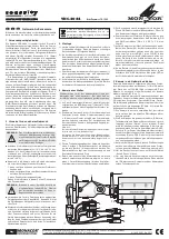
8.  Venting is required to keep burner electronics from overheating. 

Venting is achieved with air holes located at the bottom of the fire pit 

walls as shown in Figures 5, 6, 7 and 8.

NOTE: 

Providing good drainage is critical. Fire Pits using propane should 

not have drains located at bottom of cavity. Drainage should be 

achieved with vent holes located at bottom of side walls as shown 

in Figures 6 and 8.

IMPORTANT: 

There is an 18” minimum depth requirement on residential 

fire pits and 24” minimum depth on commercial fire pits as 

shown in Figures 5, 6, 7 and 8.

9.   On commercial installations, it is recommended to install a keyed 

switch and kill switch located in close proximity and in visible sight of 
feature or features. The keyed and kill switches must be electrically 
wired into the 110v upstream of the Grand Effects

®

 Control Panel.

X1

X2

GRD

1” GAS BALL VALVE

OR KEYED VALVE

INSTALLED ON

FIRE PIT

1” NPT

GAS INLET

REDUCE

TO 3/4”

DRAIN

SUPPORT

THREADED ROD

REMOVE EXCESS

AFTER INSTALLING NUT

FIRE PIT WALL

2.5” DIA. (4)

MULTIPLE VENTS

REQUIRED

TO GRAND EFFECTS

CONTROL PANEL

24” MIN.

39” MIN. FOR 24” BURNER

43” MIN. FOR 30” BURNER

2”

Figure 7. 

Natural Gas - Commercial Installation

X1

X2

GRD

 1” GAS BALL VALVE

OR KEYED VALVE

INSTALLED ON

FIRE PIT

1” NPT

GAS INLET

REDUCE

TO 3/4”

SUPPORT

THREADED ROD

REMOVE EXCESS

AFTER INSTALLING NUT

FIRE PIT WALL

2.5” DIA. (4)

MULTIPLE VENTS

REQUIRED

TO GRAND EFFECTS

CONTROL PANEL

24” MIN.

2”

39” MIN. FOR 24” BURNER

43” MIN. FOR 30” BURNER

Figure 8. 

Propane - Commercial Installation

Summary of Contents for FPIAUT24

Page 1: ...death Improper installation and or operation can create carbon monoxide gas and flue gases which can cause serious injury property damage or death For installations in the vicinity of occupied living spaces as an additional measure of safety Zodiac Pool Systems LLC strongly recommends installation of suitable carbon monoxide detectors in the vicinity of this appliance and in any adjacent occupied ...

Page 2: ...he Grand Effects 24 30 Fire Pit Inserts 5 3 1 Preparing the Fire Pit Inserts for Installation 5 3 2 Gas and Electric Requirements 6 3 3 Installing the Fire Pit Inserts 7 Section 4 Burner Setup and Adjustment 14 4 1 Burner Setup 14 4 2 Burner Adjustment 15 Section 5 Maintenance 16 Section 6 Operation 17 6 1 Operating Instructions 17 Section 7 Troubleshooting 18 Section 8 Control Module Diagram 21 S...

Page 3: ...or Grand Effects at 949 697 5270 DANGER RISK OF ELECTRICAL SHOCK OR ELECTROCUTION This fire pit must be installed by a licensed or certified electrician in accordance with the National Electrical Code and applicable local codes and ordinances In Canada the Canadian Electrical Code and all applicable local codes and ordinances must be adhered to Improper installation will create an electrical hazar...

Page 4: ...Burner Assembly must be sent back to a Grand Effects service center for repair A certified gas professional should remove and re install the Fire Box Burner Assembly 2 2 Product Contents 1 3 2 1 Support Plate Qty 1 2 Burner Assembly Qty 1 3 Grand Effects Fire Pit Inserts Automated Operation and Maintenance Manual Qty 1 WARNING RISK OF ELECTRICAL SHOCK OR ELECTROCUTION which could result in serious...

Page 5: ...Pit Inserts for Installation NOTE The electrician must complete preparatory steps before fire pit is installed The National Electrical Code NEC allows listed low voltage gas fired luminaires decorative fireplaces fire pits and similar equipment using low voltage ignitors that do not require grounding and are supplied by a listed transformer power supply with outputs that do not exceed the low volt...

Page 6: ...so may void the Zodiac Pool Systems LLC warranty CAUTION To prevent premature failure of the appliance resulting from stray voltages and voltage differentials the burner must be bonded to other equipment which is part of the pool plumbing system with a solid copper wire not smaller in diameter than 8 AWG 6 AWG in Canada BONDING THE BURNER Note The Burner insert contains a bonding lug near the pilo...

Page 7: ...clear of all debris such as paper leaves pine needles and other combustible materials WARNING This unit is for outdoor use only Recommended CSA AGA Clearances Sides 4 ft Top 6 ft A LP gas regulator should never be installed in the fire pit It should be installed by a gas expert in a remote location away from the heat source Install burner assembly out of the way of pedestrian traffic Installation ...

Page 8: ...and each burner as shown in Figure 2 3 and 4 GAS INLET CONNECTION MANUAL GAS VALVE 120 VAC 60HZ INPUT TO CONTROL PANEL CONTROL PANEL TYPICALLY MOUNTED WITH POOL EQUIPMENT UP TO 150 FEET FROM BURNER 2 VAC OUTPUT CONDUIT UNDERGROUND 1 NPT GAS PIPING UNDERGROUND Figure 2 Natural Gas CONTROL PANEL TYPICALLY MOUNTED WITH POOL EQUIPMENT GAS INLET PROPANE GAS OUTLET 24 VAC OUTPUT CONDUIT UNDERGROUND 1 NP...

Page 9: ...uced to 3 4 NPT or larger at the burner as shown in Figure 5 6 and 7 4 At each burner install a 90 gas pipe elbow on the gas line for proper installation of a gas hose Do not kink or make a tight radius bend on the gas hose IMPORTANT Do not come straight up with the gas hose As shown in Figure 5 6 and 7 a 90 gas pipe elbow must be installed on the gas line for proper installation of the gas hose T...

Page 10: ...rol panel 6 Maintain good piping practice by keeping pipe length and elbows to a minimum to eliminate unnecessary pressure drops Corrugated flex gas lines should not be used 7 The Support Plate can be installed in a few different methods Smaller Support Plates can be supported using legs threaded rod supplied by Grand Effects When using threaded rod adjust the height of the support plate as shown ...

Page 11: ...tall a keyed switch and kill switch located in close proximity and in visible sight of feature or features The keyed and kill switches must be electrically wired into the 110v upstream of the Grand Effects Control Panel X1 X2 GRD 1 GAS BALL VALVE OR KEYED VALVE INSTALLED ON FIRE PIT 1 NPT GAS INLET REDUCE TO 3 4 DRAIN SUPPORT THREADED ROD REMOVE EXCESS AFTER INSTALLING NUT FIRE PIT WALL 2 5 DIA 4 ...

Page 12: ... the connections wrap the wire nut connections with NRTL listed certified electrical tape Install electrical Burner Ground and Burner Spark from Sub panel to burner 12 Install pilot and main gas hoses from Sub panel to Burner Assembly With all gas connections tight position the burner assembly so that it sits level on the Support Plate DRAIN PILOT GAS BURNER ASSEMBLY FIRE PIT WALL 2 5 D 4 MULTIPLE...

Page 13: ...E MAIN GAS BURNER SPARK BURNER GROUND 39 MINIMUM FOR 24 BURNER 43 MINIMUM FOR 30 BURNER Figure 11 Natural Gas Commercial Installation DRAIN PILOT GAS BURNER ASSEMBLY FIRE PIT WALL 2 5 D 4 MULTIPLE VENTS REQUIRED GAS ELECTRICAL 18 MIN 2 SUB PANEL MOUNTED TO FLOOR PROVIDE ADEQUATE DRAINAGE MAIN GAS BURNER SPARK BURNER GROUND 39 MINIMUM FOR 24 BURNER 43 MINIMUM FOR 30 BURNER Figure 12 Propane Gas Com...

Page 14: ...by adjusting the ball valve or keyed valve 8 Install decorative rock or glass on top of the burner support and burner assembly Larger lava rock is recommended 2 4 in size It will work better than smaller rock Make sure that all rock is clear of the pilot area and hood area Pilot hood area needs to remain clear of rock for proper ventilation NOTE Do not use glass with propane installations If you u...

Page 15: ...minals X1 X2 located in Grand Effects control panel There should be no power at the burner assemblies when purging propane The propane adder valve should remain wired and energized when purging After purging is complete make sure the area is vented and free from built up gas Reinstall wires at X1 X2 terminals thus providing power to burner assemblies 4 2 Burner Adjustment Note The burner should ha...

Page 16: ...t all gas connections are tight The units should be cycled frequently especially after a rain The burner assembly will not work in snow and ice conditions The burner assembly should be covered and protected from snow and ice The burner should not be operated in high wind conditions High winds can limit the cooling air required for cooling of the burner assembly and cause over heating of the electr...

Page 17: ...reme care and at your own risk Before any inspection of the unit always turn off power and gas supply at the control panel If you experience problems with this unit call Grand Effects or a licensed heating professional All work on this unit must be performed by a licensed heating professional WARNING To avoid the risk of property damage and serious injury including death before you turn on the Gra...

Page 18: ...tep Symptom Corrective Action Main burner does not light no spark 1 Remove rock glass away from pilot area Look for small pieces obstructing pilot 2 If still no spark confirm that you have 12VAC out of the panel and at the burner 3 If you have voltage going out to the burner but no spark replace the ignition module 4 If you have no voltage out of the panel replace the transformer Spark but no pilo...

Page 19: ...owing across pilot 2 If using glass make sure an open pilot hood is used Remove rock glass away from pilot area Does it get better How much glass Thin down glass on burner assembly 3 Remove all rock glass from the burner assembly Does the problem go away 4 If gas pressure is too low or main burner is adjusted too low the pilot will be too small and unstable 5 If burner shuts off after a 30 minute ...

Page 20: ...dule Diagram GRAND EFFECTS Fire and Water Features www grandeffects com 12VAC 50 60Hz 1 3A IV 2 5A GE1020FB12V 2021 116 REV B S O 0027352 1840 THIS CONTROL IS TO BE USED WITH OUTDOOR APPLIANCES ONLY MV PV GND VALV GND SPRK GND X2 TH X1 FC FC 1 45 5 25 GRAND EFFECTS GE1020 CONTROL MODULE ...

Page 21: ...24 30 Fire Pit Inserts Standard Line Automated Operation Page 21 Section 9 Wiring Diagram BLACK WHITE 120V BLACK 120V WHITE GREEN GROUND BURNER GREEN X2 ORANGE X2 ORANGE X1 BLACK X1 BLACK CONTROL PANEL ...

Page 22: ...Page 22 24 30 Fire Pit Inserts Standard Line Automated Operation NOTES ...

Page 23: ...24 30 Fire Pit Inserts Standard Line Automated Operation Page 23 NOTES ...

Page 24: ...U used under license All other trademarks are the property of their respective owners H0667600 REV A Zodiac Pool Systems LLC 2882 Whiptail Loop 100 Carlsbad CA 92010 1 800 822 7933 www ZodiacPoolSystems com Grand Effects 23121 Arroyo Vista Suite B Rancho Santa Margarita CA 92688 1 949 697 5270 www GrandEffects com ...

Reviews: