background image

LL200 Compressor Installation 

12

332230T

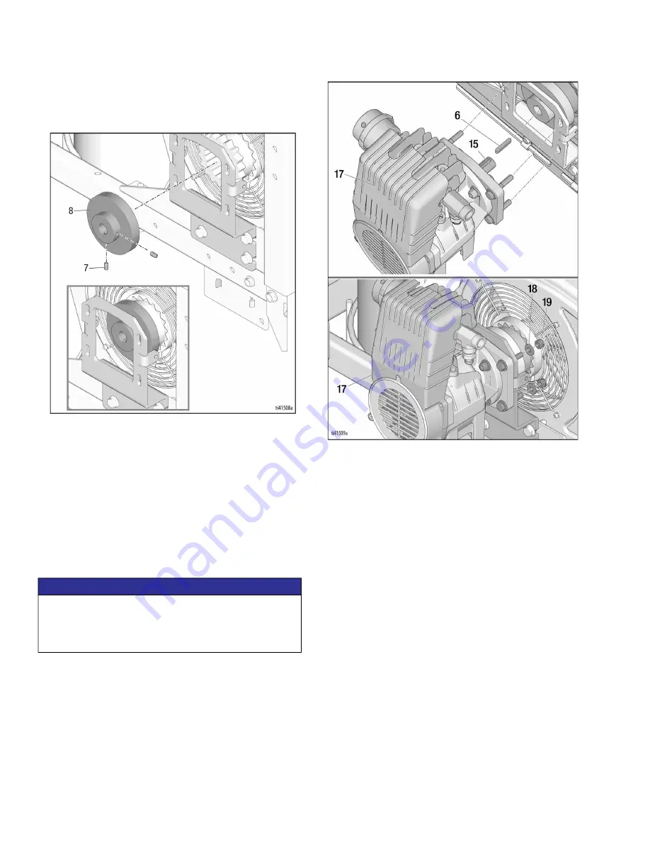
16. Start two set screws (7) into second coupler (8). 

Slide coupler (8) over flex insert (9). Coupler (8) 

should stay in position, if not it may need to be held 

until the next step.

17. Ensure keyway on coupler shaft (15) is on top, 

rotate as necessary. Place second key (6) in 

keyway of coupler shaft (15). Align keyway in 

coupler (8) to receive coupler shaft (15) and key (6). 

Aligning all four studs (16) with associated vertical 

slots, slide compressor assembly (17) into 

mounting bracket so that coupler shaft (15) inserts 

into coupler (8), ensure key (6) stays in place. Install 

four washers (18) and four nuts (19) onto four studs, 

tighten until slightly loose to allow for vertical 

adjustment.

18. Horizontal Alignment: hold compressor assembly 

(17) such that when viewed from above both 

couplers (8) and flex insert (9) are aligned axially. 

When properly aligned, tighten mounting bracket 

bolts (11) to frame to 23-27 ft-lbs (31-37 N•m). 

Horizontal alignment is now complete.

NOTICE

Performing the following step incorrectly may result in 

improper alignment of the two rotating couplers. This 

may cause premature wear and require replacement 

of the flex insert (9).

Summary of Contents for LineLazer 200DC

Page 1: ...LL200HS DC MMA 25R269 2 Gun LL250SPS DC MMA 80 psi 55 MPa 5 5 bar Maximum Working Pressure Important Safety Instructions Read all warnings and instructions in the striper manual Be familiar with the controls and the proper usage of the equipment Save these instructions Related Manual Bead Gun Kit 332226 LLIV 200HS Repair 311021 LLV 200HS DC Repair and Parts 3A3390 LLV 200MMA Operation Repair Parts...

Page 2: ...UIPMENT MISUSE HAZARD Misuse can cause death or serious injury Do not operate the unit when fatigued or under the influence of drugs or alcohol Do not exceed the maximum working pressure or temperature rating of the lowest rated system component See Technical Data in all equipment manuals Use fluids and solvents that are compatible with equipment wetted parts See Technical Data in all equipment ma...

Page 3: ...sure Relief Procedure and disconnect all power sources MOVING PARTS HAZARD Moving parts can pinch cut or amputate fingers and other body parts Keep clear of moving parts Do not operate equipment with protective guards or covers removed Pressurized equipment can start without warning Before checking moving or servicing equipment follow the Pressure Relief Procedure and disconnect all power sources ...

Page 4: ... Read and understand all warnings and instructions in this manual and the striper manual Tools Needed 1 8 in Allen Wrench supplied with kit Alignment tool 17C504 supplied with kit 5 32 in Allen Wrench 1 4 in Allen Wrench 3 16 in Allen Wrench 7 16 in Wrench 3 8 in Wrench 1 2 in Wrench 5 8 in Wrench 9 16 in Wrench 11 16 in Wrench T 20 Torx Bit Cutting Blade Rubber Mallet Phillips Screwdriver Straigh...

Page 5: ...for LL200 and LL250 Component Identification Ref Description 1 Funnel 2 Wing Nut 3 Compressor Bypass Switch 4 Regulator Unloader 5 Pressure Relief Valve 6 Bead Tank Gauge 7 Pressure Regulator Valve 8 Air Tank Gauge 9 Safety Relief Valve Ref Description ...

Page 6: ...il it reaches end of threads If any remaining pressure is in bead tank it will be released through seal while wing nut secures lid to hopper Confirm pressure is at 0 psi 0 bar 0 MPa and open lid 4 Secure lid over opening and tighten wing nut until lid is level with hopper This equipment stays pressurized until pressure is manually relieved To help prevent serious injury from pressurized fluid such...

Page 7: ...ed on either side of sprayer 1 Turn off unit Perform Pressure Relief Procedure page 6 2 Loosely install two screws MM and two locknuts NN through bottom of frame mount but do not tighten Remove existing gun arm bracket to gain access to nut NN 3 Assemble hopper basket XX and base with hardware as shown below Use 9 16 in wrench to snug screws Loosen all six screws 1 4 turn 3A3788 ti21201a NN MM ti2...

Page 8: ...Complete Frame Assembly NOTE If desired rotate recoil 90 counter clockwise 1 Use 9 16 wrench to tighten bottom screws MM to hardware shown 2 Install plastic end caps ZZ into frame Use rubber mallet to pound end caps into place ti21500a ti21200a MM ti20884a ZZ ...

Page 9: ...4 3 Disconnect output air line 4 Using a 9 16 in wrench remove air tank from frame 5 Using same bolts bb and lock nuts 22 install air tank bracket 3 6 With a 9 16 in wrench mount air tank to air tank bracket with screws When correctly installed air tank will sit farther forward than the previous installation 3A3788 Replacing the compressor requires pulling on the starting rope To help prevent enta...

Page 10: ...5 0 225 in 3 175 5 73 mm beyond the face of the pulley The pump shaft is the pilot for the coupler adapter If necessary loosen set screws on pulley and slide pulley along pump shaft torque set screws to 58 62 in lb 6 6 7 N m NOTE Before performing step 13 secure nuts to back of pulley with piece of duct tape to assist with installation 11 Install shaft coupler 5 onto pulley with two shoulder screw...

Page 11: ...13 Start two set screws 7 into coupler 8 Slide coupler 8 over coupler mount 5 assure key 6 is still in position Push coupler 8 flush against coupler mount 3 face Tighten set screws with 1 8 in Allen wrench to 150 160 in lb 16 9 18 N m 14 Align teeth and slide flex insert 9 all the way into coupler 8 15 Secure mounting bracket 10 to frame with four flange bolts 11 Leave bolts slightly loose to allo...

Page 12: ... 17 into mounting bracket so that coupler shaft 15 inserts into coupler 8 ensure key 6 stays in place Install four washers 18 and four nuts 19 onto four studs tighten until slightly loose to allow for vertical adjustment 18 Horizontal Alignment hold compressor assembly 17 such that when viewed from above both couplers 8 and flex insert 9 are aligned axially When properly aligned tighten mounting b...

Page 13: ...lb 16 9 18 N m Verify flex insert 9 can wiggle slightly between couplers Only a slight amount of movement is required 21 Place guard 20 over mounting bracket 11 Located longest slot on vertical sides 3rd from top and align with mounting tabs Install two flat washers 21 two lock washers 22 and two screws 23 Leave slightly loose Press guard 20 flush against fan guard 24 Ensure minimal less than 1 4 ...

Page 14: ...mping band around tank and secure with mounting hardware shown below Tighten until there is no movement between clamp and bead tank NOTE The flats on the clamp are not intended to touch the hopper bracket when tightened 3 Install 36 in nylon air line dd from top of regulator to swivel fitting on top of bead hopper Cut air line to desired length Push air line into fitting until end touches bottom o...

Page 15: ...50 frame NOTE To ensure flush sitting scrape frame free of any raised debris on frame surface 3 Cut any existing tie wraps that interfere they will be replaced later with new tie straps 4 Loosely install two screws M and two locknuts N through bottom of frame mount Use 9 16 in wrench to fully tighten 5 Secure hydraulic lines with zip ties 6 Position left frame mount W on LL250 frame Remove any zip...

Page 16: ...ember 8 Use 9 16 wrench to tighten bottom screws M to hardware shown 9 Assemble hopper bracket X and base Y with hardware provided Install carriage bolts with the heads facing the paint tanks Use 9 16 in wrench to tighten bolts 2 674 10 Install plastic end caps Z into frame Use rubber mallet to pound end caps into place Inches Centimeter ti20502a ti20500a M ti24390a ti20884a Z ...

Page 17: ...16 in wrench and screws mount the air tank to the new air tank bracket 6 Remove oil breather from compressor Pour 4 oz of included compressor oil into compressor through breather port Verify oil is above red dot in sight glass NOTE Oil level will change at a slower rate than poured as it descends into the crankcase Pour small amounts at a time checking between pours 3A3788 Replacing the compressor...

Page 18: ... the coupler adapter If necessary loosen set screws on pulley and slide pulley along pump shaft torque set screws to 58 62 in lb 6 6 7 N m NOTE Before performing step 14 secure nuts to back of pulley with piece of duct tape to assist with installation 10 Install coupler mounting plate 5 onto pulley with two shoulder screws 18 and serrated nuts 19 Position slot on back of pulley up and move serrate...

Page 19: ...against coupler mount 3 face Tighten set screws with 1 8 in Allen wrench to 150 160 in lb 16 9 18 N m 12 Align teeth and slide flex insert 9 all the way into coupler 8 13 Remove existing frame bolts 12 and washers 13 from frame Using the same bolt and washers secure mounting bracket 10 to frame Leave bolts slightly loose to allow for horizontal adjustment in following steps ...

Page 20: ...is on top rotate as necessary Place second key 6 in keyway of coupler shaft 15 Align keyway in coupler 8 to receive coupler shaft 15 and key 6 Aligning all four studs 16 with associated vertical slots slide compressor assembly 17 into mounting bracket so that coupler shaft 15 inserts into coupler 8 ensure key 6 stays in place Install four washers 18 and four nuts 19 onto four studs tighten until s...

Page 21: ...et 10 to 150 160 in lb 16 9 18 N m Vertical alignment is now complete 18 With the second coupler 8 still loose on coupler shaft 15 slide coupler 8 against flex insert 9 until flex insert is tightly sandwiched between both couplers Back coupler 8 off approximately 1 16 in leaving a slight gap between coupler 8 and flex insert 9 Tighten set screws in loose coupler 8 with 1 8 in Allen wrench to 150 1...

Page 22: ... guard 24 Ensure minimal less than 1 4 in or no gap between mounting bracket 11 around perimeter Tighten two screws 23 to 130 150in lb 14 7 16 9 N m 20 Test operation of compressor by running unit Check for excessive vibration and or wobble between couplers 8 and flex insert 9 If present repeat horizontal and vertical alignment steps steps 16 and 17 21 Use a 11 16 in wrench and a 9 16 in backup wr...

Page 23: ...ponsible manner Preparation Perform the Pressure Relief Procedure page 4 Drain and dispose of fluids according to applicable regulations Refer to the material manufacturer s Safety Data Sheet Dismantle and recycle Remove motors circuit boards displays and other electronic components Recycle according to applicable regulations Do not dispose of electronic components with household or commercial was...

Page 24: ...cure with mounting hardware shown below Tighten until there is no movement between clamp and bead tank NOTE The flats on the clamp are not intended to touch when hopper bracket is tightened NOTE Position handle to best suit filling needs Loosen bolt AA to help swivel then retighten 4 Install 36 in nylon air line DD from top of regulator to swivel fitting on top of bead hopper Cut air hose to desir...

Page 25: ... gun Setting Bead Hopper Pressure The pressure regulator valve 5 controls pressure sent from the air tank to the bead tank The regulator is set to 0 pressure from the factory 1 Before charging bead tank confirm that bead tank lid is fully secured and beads have been loaded into tank 2 To increase pressure pull knob on pressure regulator valve 5 out and turn counter clockwise Watch bead tank gauge ...

Page 26: ...rt of the bead application 3 Turning the valve clockwise will delay gun opening closing time Turning the valve counter clockwise will speed up gun opening closing time To air tank Exhaust To bead gun Y X ti21326a NOTICE Never store glass beads in tank between jobs Begin the day with moisture free beads Moisture will cause glass beads to resist flow or solidify over time If moisture or condensation...

Page 27: ...ure needed to Step 3 Set air regulator to this pressure EXAMPLE a At 4 mph and 6 lb gal with 0 234 nozzle set tank pressure to 15 psi b At 4 mph and 6 lb gal with 0 281 nozzle set tank pressure to 10 psi c For 8 in width multiply weight min value 7 1 x 2 and for 12 in width x 3 Step 1 Step 2 Step 3 Step 4 Speed Bead Delivery Requirement 4 in Nozzle Size Pressure Needed 6 lb gal 8 lb gal 0 234 0 28...

Page 28: ...elease pressure from bead tank 3 Loosen wing nut 2 until it reaches end of threads If any remaining pressure is in bead tank it will be released through seal while wing nut secures lid to hopper Confirm pressure is at 0 psi 0 bar 0 MPa and open lid 4 Place funnel 1 into opening Pour beads into hopper Beads should not be filled to a height higher than shown in figure below Bead level can be viewed ...

Page 29: ...sure 332230T 29 0 to 8 in Line Setup For wider lines it may be necessary to mount bead gun as shown below 8 12 in Line Setup 2 Tank 1 Gun Setup Connect Y fitting as shown below to allow two tanks to flow into one gun ti20977a ti21258a ...

Page 30: ...mining Bead Application Pressure 30 332230T Double Drop Setup Use a Y fitting to create a dual bead gun setup for double drop beads Splice exit hose on bottom of air switch and branch into both guns ti20564a ...

Page 31: ...Notes 332230T 31 Notes ...

Page 32: ...Parts Model 25R268 32 332230T Parts Model 25R268 ...

Page 33: ... 49 16R963 KIT accessory bead gun 1 50 404989 STRAP tie 2 51 16U273 GRILL fan guard 1 52 16C394 LABEL safety warning entangle 1 53 16U025 KIT tank pressure includes 53a 53o 1 53a 156971 FITTING nipple short 2 53b 187357 ELBOW street 1 53c 16W088 GAUGE air pressure 1 53d 17C463 FITTING tee street modification 1 53e 16U375 REGULATOR 1 53f 126804 REGULATOR unloader 1 53g 162453 FITTING 1 4 NPT 1 53h ...

Page 34: ...Parts Model 25R270 34 332230T Parts Model 25R270 ...

Page 35: ...T437 FUNNEL bead tank 1 49 16R963 KIT accessory bead gun 1 51 16U327 GRILL fan guard 1 53 16U025 KIT tank pressure includes 53a 53o 1 53a 156971 FITTING nipple short 2 53b 187357 ELBOW street 1 53c 16W088 GAUGE air pressure 1 53d 17C463 FITTING tee street modification 1 53e 16U375 REGULATOR 1 53f 126804 REGULATOR unloader 1 53g 162453 FITTING 1 4 NPT 1 53h 16U174 TANK pressure 1 53i 101970 PLUG pi...

Page 36: ... disclose any defect in material or workmanship repairs will be made at a reasonable charge which charges may include the costs of parts labor and transportation THIS WARRANTY IS EXCLUSIVE AND IS IN LIEU OF ANY OTHER WARRANTIES EXPRESS OR IMPLIED INCLUDING BUT NOT LIMITED TO WARRANTY OF MERCHANTABILITY OR WARRANTY OF FITNESS FOR A PARTICULAR PURPOSE Graco s sole obligation and buyer s sole remedy ...

Reviews: