Appendix I - Communications Gateway Module Installation Kit
3A2175Z
117
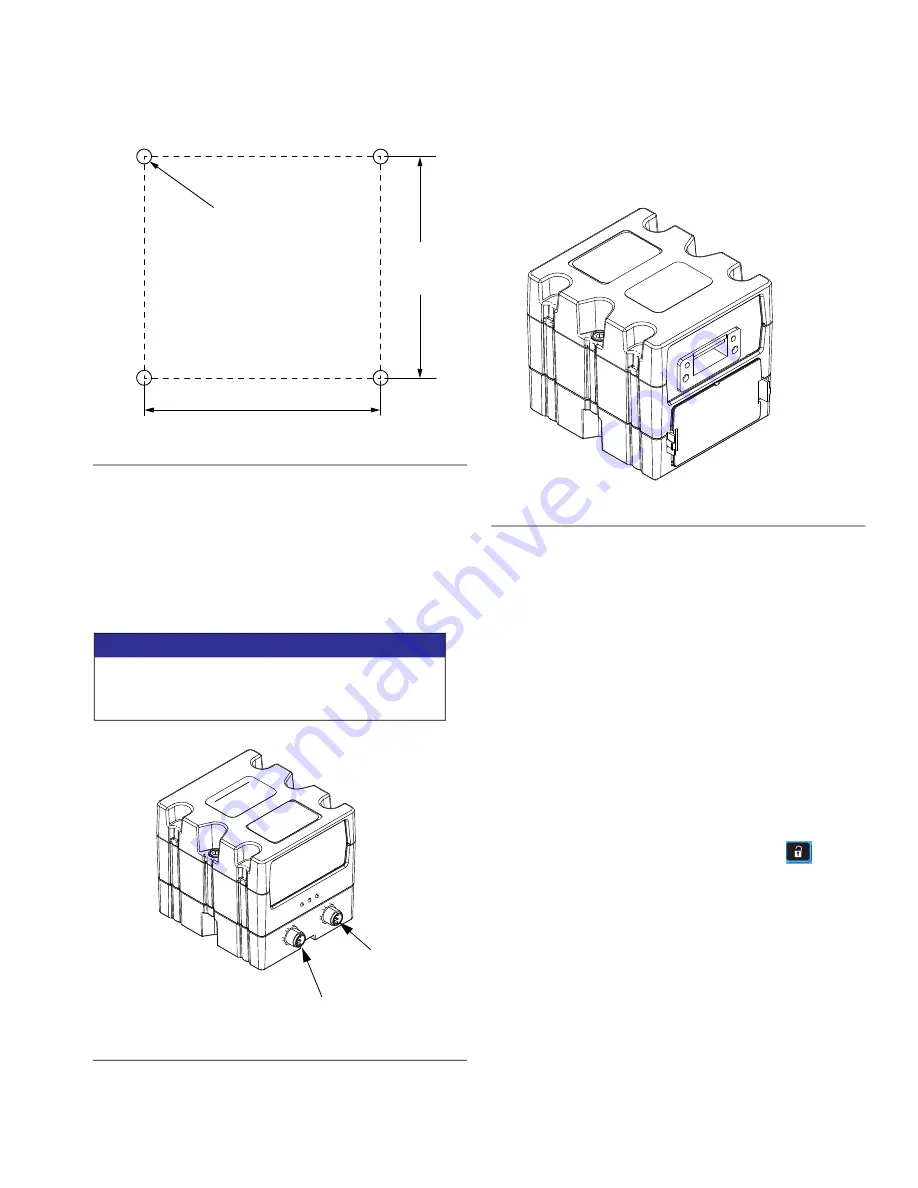
3. Mount CGM (A) on base (B) with two screws (C).
4. Install access cover (D).
5. Connect CAN cable from either CAN connection on
the CGM to the CAN connection found on the CGM
to the CAN connection found on the bottom of the
ADM. See F
6. If Used, connect the Ethernet, DeviceNet, or
Profibus cable to the CGM as applicable. Connect
the other end of the cable to the FIeldBus device.
See F
.
7. Perform the Install or update data map procedure
in Communications Gateway Module, Instructions
and Parts manual 312864.
8. See
, page 120 for details
on FieldBus pinout setup.
9. Perform the setup to configure the FieldBus.
Setup - Gateway Screens
The gateway screens are used to configure the
fieldbus. These screens are shown only if a CGM is
correctly installed in your system. See
page 116.
1. With the system on and enabled, press
to
access the setup screens.
2. Press the left arrow key once to navigate to the
main gateway screen. See F
EtherNet/IP FieldBus Screens
These screens are shown only if you have EtherNet/IP
FieldBus CGM installed.
F
IG
. 49
NOTICE
To avoid severe damage to CGA modules, ensure
the CAN cable is connected to the appropriate
CAN connection.
F
IG
. 50
2.75 in.
(69.9 mm)
3.25 in.
(82.6mm)
#10-32 UNF
(M5 x 0.8)
CAN
Connector 1
CAN
Connector 1
F
IG
. 51
Summary of Contents for HFRL
Page 13: ...Warnings 3A2175Z 13...
Page 137: ...Accessories 3A2175Z 137...


