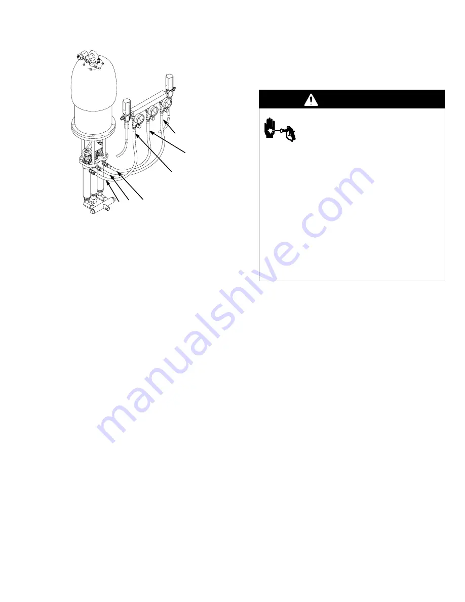
background image

307132

7

Installation

TI0645

Ensure hoses are routed correctly
during installation with three dis-
placement pump models.

A

A

B

A

A

B

NOTE: 

See page 22 for accessories mentioned in this

section.

In the following instructions, the base fluid will always
be called part A and the catalyst will be called part B.
With three displacement pump models, always use the
two outer displacement pumps to supply part A and
the middle displacement pump to supply part B.

Mount pump to suit the type of installation planned.
Accessory wall mounting bracket is shown on page 22,
pump dimensional drawing and mounting hole layout
are shown on page 24. When mounting pump on wall,
be sure the wall is strong enough to support the pump
and other equipment, plus any stress developed when
equipment is operating. Drill three 3/16 in. diameter
holes in mounting bracket as shown on page 24. Using
screws (43 or 56), screw manifold (49 or 62) onto
bracket.

Connect part A inlet hose to 3/4 npt inlet of manifold on
three displacement pump models, or to 3/4 npt inlet of
left hand displacement pump on two displacement
pump models. Connect part B inlet hose to 3/4 npt
swivel union inlet of center displacement pump mod-
els.

System Accessories

Install the accessories in the order shown in the 

Typi-

cal installations

 on pages 5 and 6. Working up-

stream from the pump inlet, install a pump runaway
valve (B) to shut off the air to the pump if the pump
accelerates beyond the pre-adjusted setting. A pump
which runs too fast can be seriously damaged.

Next, install an air line lubricator (C) for automatic air
motor lubrication, a bleed-type master air valve (A) to
relieve air trapped between the valve and the pump, an
air regulator (D) to control pump speed, and an air filter
(E) to remove harmful dirt and moisture from the com-
pressed air supply.

Install a fluid drain valve (G) at each fluid outlet to re-
lieve pressure in the system. Be sure the valve is
pointed downward.

WARNING

INJECTION HAZARD

Two accessories, the bleed-type master
air valve (A) and the fluid drain valve (G)
are required for your system to reduce

the risk of serious injury from moving parts, fluid
injection, or splashing when shutting off the pump.

The bleed-type air valve relieves air trapped be-
tween the valve and the pump, after the pump is
shut off. Trapped air can cause the pump to cycle
unexpectedly and result in serious injury if you are
adjusting or repairing the pump.

The fluid drain valve helps relieve fluid pressure in
the displacement pump, hose and gun when shut-
ting off the pump. Triggering the gun to relieve
pressure may not be sufficient, especially if there is
a clog in the hose, gun/dispensing valve, or tip/
nozzle.

Install and connect feed pumps, solvent pump, mixer,
etc. See 

Typical installations

 on pages 5 and 6

and separate component instructions.

Feed Systems

Material supply must be pressure fed into each propor-
tioning cylinder. If materials require heating they can
be heated in the supply feed as well as the outbound
side of the pumps. Material supply is critical to proper
proportioner operation. Material must fill the proportion-
er cylinders on their upstroke totally to elimiate a “div-
ing” of the cylinders on the top change–over. This “div-
ing” will also be seen as a pressure drop at the change
over. This will cause an off ratio condition.

Ensure your feed systems are designed to supply
twice the volume used by each componet. This supply
pump pressure should never exceed 25% of the pro-
protioner output pressure.

Example:

 4:1 proportioner. 2.0 gpm output, 1000 psi.

4:1 ratio at 2.0 gpm = 1.5gpm of “A” component and
1/2 (.5) gpm of component “B”.

“A” feed pump needs to have a 4 gpm capacity
at a max of 250psi.

B" feed pump needs to be at least 1 gpm at

250 psi max.

Review your feed systems with your Graco Distributor.

Summary of Contents for BULLDOG HYDRA-CAT 208958

Page 1: ...l 209000 Series E 2 1 Mix Ratio Model 209001 Series E 3 1 Mix Ratio Model 209002 Series E 4 1 Mix Ratio Model 209003 Series E 2 1 2 1 Mix Ratio RELIEF VALVE INSTALLATION KITS Required for safe operati...

Page 2: ...tatic sparking or you feel an electric shock while using this equipment stop spray ing immediately Do not use the equipment until you identify and correct the problem Provide fresh air ventilation to...

Page 3: ...the equipment Check the hoses tubes and couplings daily Replace worn damaged or loose parts immediately Permanently coupled hoses cannot be repaired replace the entire hose Use only Graco approved ho...

Page 4: ...uid pressures to be achieved A 475 to 575 psi working pressure range relief valve is provided on the secondary side to limit the fluid pressure Do not tamper with this pressure relief valve or serious...

Page 5: ...25 For pressure feed to proportioning pump mount fluid pressure gauges at proportioning pump inlets to properly adjust feed pump pressures 1 1 D A C N E A B A D A M F P F J G G C B H PART A PART B LIG...

Page 6: ...pressures 1 KEY A Bleed type master air valve B Pump runaway valve C Air line lubricator D Air regulator E Air line filter F Fluid filter G Fluid drain valve H Feed pump J Proportioning pump K Solvent...

Page 7: ...m pressed air supply Install a fluid drain valve G at each fluid outlet to re lieve pressure in the system Be sure the valve is pointed downward WARNING INJECTION HAZARD Two accessories the bleed type...

Page 8: ...pt m fluid outlets of relief valves Fig 1 05227 3 8 npt m Part A Fluid Outlet 3 4 npt m Part A Fluid Inlet 3 8 npt m Part B Fluid Outlet 3 4 npt m Part B Fluid Inlet Part A Part B D A G C B G 209005 R...

Page 9: ...nding Wire and Clamp P N 237569 25 feet 7 6 m long 12 ga 2 Air and fluid hoses Use only electrically conduc tive hoses with a maximum of 500 feet 150 m combined hose length to ensure grounding conti n...

Page 10: ...gh pressure can be injected through the skin and cause serious injury To reduce the risk of an injury from injection splashing fluid or moving parts follow the Pressure Relief Procedure whenever you a...

Page 11: ...o use When clean solvent is coming out of the gun dispensing valve re move the solvent supply from the feed pumps intakes Slowly run the pump to push all the solvent out of the lines then stop the pum...

Page 12: ...n the eyes or on the skin and property dam age never exceed the maximum air and fluid work ing pressure of the lowest rated component in your system See page 10 Reconnect the fluid dispensing hose to...

Page 13: ...king nut should be tight enough to prevent leakage no tighter Too tight an adjustment will cause the packings to bind or wear prematurely and leak Relieve the pres sure before adjusting the packing nu...

Page 14: ...or for assistance in selecting the proper type of flow restrictor for your application 1 Disconnect the fluid hoses from the mixer inlet valves taking note of which hose was connected to which valve T...

Page 15: ...s 9 from the intakes of the displacement pumps and remove the manifold 20 3 Remove the two retaining nuts 6 from the two outer pumps displacement rods E Screw the fluid pump retaining rings 15 off the...

Page 16: ...5 222012 24 1 0 064 0 24 2400 16 8 168 100 0 7 7 3 1 222012 222017 222012 25 1 0 061 0 23 2500 17 170 100 0 7 7 4 1 222012 222019 222012 27 1 0 057 0 22 2500 17 170 93 0 6 6 4 Exceeds the pressure rat...

Page 17: ...307132 17 Notes...

Page 18: ...n manual 307049 Displacement pump seized Service lower pump see instruction manual 307944 System speeds up or runs erratically Fluid containers are empty Check often keep filled Air in fluid lines Pur...

Page 19: ...nder on upstroke diving on top of change over Increase pressure on feed pump Check inlet filter screen Check foot valve Pump operates but part B output pres sure drops during both strokes Dirty worn o...

Page 20: ...t pumps and remove the manifold 20 3 Remove the two locknuts 6 from the two outer pumps displacement rods E Screw the fluid pump retaining rings 15 off the fluid pumps use a screwdriver and hammer to...

Page 21: ...ining rings 15 and washers 14 Thread the displacement rods into the yoke 13 by turning the complete cylinder Install the locknuts 6 loosely on the displacement rods Push the cylinders up into place in...

Page 22: ...4 in 101 6 mm 3 16 in 5 mm dia bolt circles 3 holes 6 9 in 175 3 mm 6 9 in 175 3 mm Throat Seal Liquid Non evaporating solvent for wet cup 206994 8 oz 0 2 liter 206995 1 qt 0 9 liter 206996 1 gal 3 8...

Page 23: ...307132 23 Notes...

Page 24: ...t f fluid outlets 3 4 npt fluid inlets 3 4 npt f air inlet 45 in 1143 mm 23 in 584 mm Mounting Hole Layout 05235 9 in 229 mm diameter 0 44 in 11 2 mm diameter 4 holes 10 5 in 267 mm diameter bolt circ...

Page 25: ...d parts Stainless Steel Tungsten Carbide Chrome Plating Carbon Steel Ultra High Molecular Weight Polyethylene NEVER exceed 2500 psi 17 MPa 170 bar fluid pressure Air Consumable Example When the air pr...

Page 26: ...including but not limited to incidental or consequential damages for lost profits lost sales injury to person or property or any other incidental or consequential loss shall be available Any action f...

Reviews: