332298J
EN
Instructions
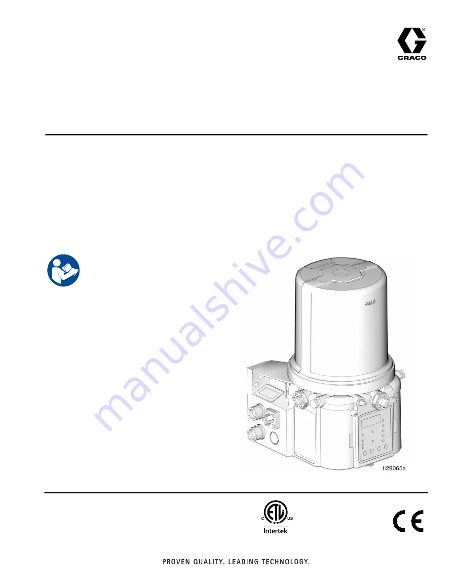
G3
™
Pro Automatic
Lubrication Pump
For dispensing NLGI Grades #000 to #2 greases and oil with at least 40cSt. For
Professional Use Only.
Not approved for use in explosive atmospheres or hazardous (classified) locations.
Part Nos., page 3
5100 psi (35.1 MPa, 351.6 bar) Pump Output Pressure
5000 psi (34.4 MPa, 344.7 bar) Fill Inlet Pressure
Important Safety Instructions
Read all warnings and instructions in this
manual. Save all instructions.
Conforms to ANSI/UL 73
Certified to CAN/CSA
C22.2 No 68
3132066
24V and 100-240VAC Pumps ONLY