background image

6

308647

Installation

H

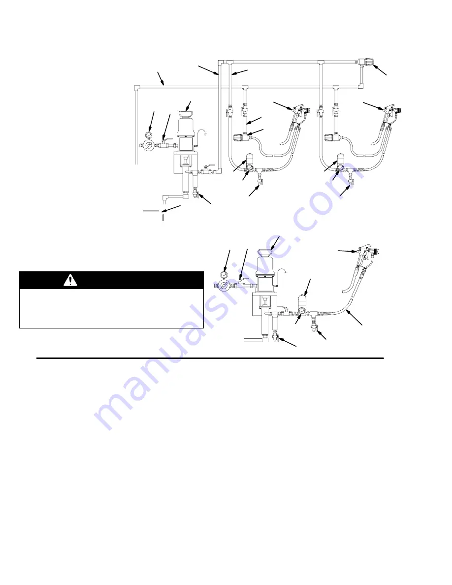
Multiple Circulating Spray Station

Key

Air regulator
Bleed-type master air valve
Pump
Fluid filter and drain valve
E

Main fluid supply line

F

Gun fluid supply line

Fluid regulator

with fluid pressure gauge (H)

Fluid pressure gauge
J

Air-assisted airless spray gun

Back pressure valve
L

Fluid return line

Main circulating line
Fluid supply container
P

Drain valve

A

B

C

D

E

F

J

K

M

K

L

A

B

C

G

D

J

Single Direct Spray Station

G

N

F

Fig. 1

06461

J

P

G

P

06462

P

H

H

WARNING

Do not use PTFE tape on pipe threads.  Such use
could cause a hazardous condition due to loss of
grounding continuity.  Also, if pieces of the tape break
off, the function of the regulator could be affected.

The installations shown in Fig. 1 are only a guide for
selecting and installing a circulating or direct system;
they are not actual system designs.  Contact your
Graco distributor for assistance in designing a system
to suit your needs.

NOTE:  Before you install the regulator, thoroughly
flush the system to remove metal chips and other
contaminants.  A fluid filter (D) of 60-mesh or finer
should always be installed upstream of the regulator.

Connections

Install the fluid regulator (G) in the spray gun fluid
supply line (F), as shown in the typical installation
drawings on this page.  Connect only one spray gun
or dispensing valve to each fluid regulator.

Apply pipe sealant to the male pipe threads, and
connect the fluid supply line (F) to the fluid regulator’s
3/8 npt(f) inlet.  Connect the line from the gun (J) to the
fluid regulator’s 3/8 npt(f) outlet.  Install the gauge or
plug into the 1/4 npt(f) gauge port.

Make sure the direction of fluid flow agrees with the IN
and OUT markings on the regulator body.

Flush the System

The regulator was tested in lightweight oil.  Flush the
entire system with a solvent compatible with the fluid
being dispensed.  Then test the system.

Mounting Bracket

A Mounting Bracket is available for mounting the
regulator.  Order Part 222515 for the bracket and
mounting hardware.

Summary of Contents for 238889

Page 1: ...ons Parts List 06540A 06288 06290 Model 238890 238892 spring operated Model 238894 air operated Important Safety Instructions Read all warnings and instructions in this manual Save these instructions...

Page 2: ...bar 3000 5000 psi 21 34 MPa 207 345 bar 238892 with fluid pressure gauge High 6000 psi 41 MPa 414 bar 3000 5000 psi 21 34 MPa 207 345 bar Air Operated Models Part No Description Range Maximum Inbound...

Page 3: ...or modify this equipment Use only genuine Graco parts and accessories D Check equipment daily Repair or replace worn or damaged parts immediately D Do not kink or over bend the hose or use the hose t...

Page 4: ...nt D Tighten all fluid connections before operating the equipment D Check the hoses tubes and couplings daily Replace worn or damaged parts immediately Do not repair high pressure couplings you must r...

Page 5: ...5 308647 Notes...

Page 6: ...ance in designing a system to suit your needs NOTE Before you install the regulator thoroughly flush the system to remove metal chips and other contaminants A fluid filter D of 60 mesh or finer should...

Page 7: ...eing sprayed Follow your local code Solvent pails used when flushing Follow your local code Use only metal pails which are conductive placed on a grounded surface Do not place the pail on a nonconduct...

Page 8: ...re For increased sensitivity in pressure set point performance an alternative air regulator such as Part 206197 may be used This alternative air regulator uses a sensitive diaphragm design to maintain...

Page 9: ...ure of the lowest rated system component Remove the gauge if the flushing pressure will exceed the gauge range 4 Open the fluid regulator fully a Spring Operated Regulators Only Open the fluid regulat...

Page 10: ...l Replace the o ring under the seat Damaged or clogged air regulator or line air operated regulator only Clear obstruction in line Service regula tor if necessary Leaking or dirty seat Replace cartrid...

Page 11: ...spring operated model to a high pressure range spring operated model or vice versa order the appropriate spring 11 from the Parts List on page 15 Installing the Air Operated Conversion Kit See Parts D...

Page 12: ...6 Remove the o ring 17 from the groove in the base housing 4 clean and inspect the base housing and replace if necessary 7 Install a new o ring 17 in the groove in the base housing 4 8 Lightly lubrica...

Page 13: ...ssembly out of the base housing 4 NOTE The retaining nut 3 often loosens when removing the cartridge assembly from the base housing Be sure to re torque as described in step 4 3 Inspect and clean the...

Page 14: ...2 3 4 5 Torque to 10 to 20 ft lb 14 to 27 NSm Torque to 30 to 35 ft lb 41 to 48 NSm Torque first to 20 to 25 ft lb 27 to 34 NSm then to 30 to 35 ft lb 41 to 48 NSm in the sequence shown in DETAIL at l...

Page 15: ...4 191914 SEAT valve 1 15 113651 O RING packing PTFE 1 16 112365 BALL 1 17 109213 O RING packing PTFE 025 1 Ref Part No Description Qty 18 107079 O RING packing PTFE 019 1 19 O RING packing PTFE 013 1...

Page 16: ...12 13 19 14 n 15 n 18 n 20 n 17 28 29 31 32 33 35 37 36 1 2 3 4 5 Torque to 140 to 160 in lb 16 to 18 NSm Torque to 15 to 20 ft lb 20 to 27 NSm Torque to 30 to 35 ft lb 41 to 48 NSm Torque first to 2...

Page 17: ...025 1 18 n 107079 O RING packing PTFE 019 1 19 O RING packing PTFE 013 1 20 n 109450 O RING packing PTFE 016 1 Ref No Part No Description Qty 21 n 111858 SPRING compression 1 22 160062 SPRING stabiliz...

Page 18: ...36 1 2 3 4 Torque to 140 to 160 in lb 16 to 18 NSm Torque to 15 to 20 ft lb 20 to 27 NSm Torque to 30 to 35 ft lb 41 to 48 NSm 1 2 3 3 4 5 5 Torque to 170 to 190 in lb 19 to 21 NSm in alternating patt...

Page 19: ...6 15D092 BALL 1 17 109213 O RING packing PTFE 025 1 Ref No Part No Description Qty 18 107079 O RING packing PTFE 019 1 19 O RING packing PTFE 013 1 20 109450 O RING packing PTFE 016 1 21 111858 SPRING...

Page 20: ...ar 0 5000 psi 0 34 MPa 0 345 bar 0 5000 psi 0 34 MPa 0 345 bar Maximum flow in 65 cp material 2 gpm 7 6 lpm 2 gpm 7 6 lpm 2 gpm 7 6 lpm 2 gpm 7 6 lpm Maximum fluid viscosity up to 15 000 cp up to 15 0...

Page 21: ...W psi MPa bar Test Conditions Regulators tested in oil at 70_ F 21_ C and at 6000 psi 41 MPa 414 bar inbound fluid pressure Key 65 cp oil 3000 cp oil REGULATED outbound FLUID PRESSURE gpm lpm 1 9 Flui...

Page 22: ...22 308647 Notes...

Page 23: ...B A A Height 10 0 in 254 mm B Diameter of diaphragm cover 7 0 in 179 mm B 3 8 npt outlet port 3 8 npt inlet port 1 4 npt gauge port 3 8 npt 1 2 npt for 248090 inlet port 3 8 npt 1 2 npt for 248090 ou...

Page 24: ...r agrees that no other remedy including but not limited to incidental or consequential damages for lost profits lost sales injury to person or property or any other incidental or consequential loss sh...

Reviews: