background image

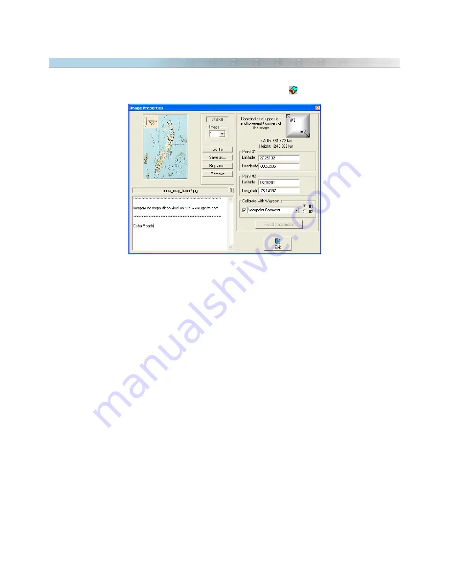
 11.5  Showing Image Properties

The 

Map Image Properties window can be accessed through the Tools menu, by clicking with left mouse button 

on the scanned image inserted in the background of the screen, or pressing

This window shows all scanned images inserted in the background of the screen and its respective characteristics,  
allowing to find the position of the image on the screen, save it to hard disk, remove it from memory, modify  
comments, modify the image file name or modify the configurations of calibration. 

To view images, just press the arrow keys up or down, or type the index number of image.

The 

Map Image Properties function will show:


Map image or scanned Photo 

Index of each scanned image 

Size of the image file in KB

File name of the scanned image 

Image comments

Virtual Width and height of the image on the screen

Points of calibration of upper-left and lower-right corners

Available Buttons: 

<Go To>

: Shows the image centered on screen.

<Save As>

: Saves the image in disk 

<Replace>

: Replaces the image to another, maintaining the same coordinates of the first image

<Remove>

: Removes the image from the memory 

<Exit>

: Closes the window 

<Recalibrate Image>

 : Makes a new image calibration through the indicated points

In GTM PR®, the 

<Save as> 

button allows to save the image in its original format or to convert the image to 

other formats.  See the topic 

Saving Images

.

136

Summary of Contents for TrackMaker

Page 1: ...1 www trackmaker com ...

Page 2: ... 3 1 Creating Editing and Deleting Waypoints 34 3 2 Editing Waypoint Styles 37 3 3 Selection of Waypoints Through Icons 39 3 4 Modifying Several Waypoints at the Same Time 39 3 5 Treating Repeated Waypoints 40 3 6 Converting Waypoint Text to Lowercase 41 4 Tracklogs 42 4 1 Creating Editing and Deleting Tracklogs 42 4 2 Selecting Tracklogs by Style 47 4 3 Editing Several Tracklogs at the Same Time ...

Page 3: ...rement 98 9 6 Configuring the Speed Unit 99 9 7 Configuring the Surface Unit of Measurement 100 9 8 Configuring the Azimuth Angle 101 9 9 Configuring Local Time 101 9 10 Configuring the Coordinate System 102 9 11 True Grid Mode 105 9 12 Configuring Images 107 9 13 Configuring the Altitude Profile 109 9 14 Configuring the Datum 110 9 15 Datum Defined by User 112 9 16 Grid Defined by User 113 9 17 D...

Page 4: ... in RTN Mode 150 13 3 Configuring Real Time Navigation 151 13 4 Registering Waypoints in Real Time 153 13 5 Simulating Real Time Navigation 153 13 6 Vehicular Tracking Interface 153 14 Printing Data 154 14 1 Print Preview 154 14 2 Printing Data 155 14 3 Printing in Scale 156 14 4 Configuring Printing 157 14 5 Printing List of Data 158 15 Catalog of Images 159 15 1 Creating a Catalog of Images 159 ...

Page 5: ...t Zoom in Zoom out and specific area Zoom functions Move the whole drawing just by pressing the right mouse button Management of more than 200 different color icons Display Waypoints on screen in several different styles Selectable colors for background grid Waypoints and Tracklogs Allows selective deletion of data either by exclusion or inclusion GPS Macro function specially created to eliminate ...

Page 6: ...on factoring altitude changes for the horizontal projection Topographical conversion function for data obtained by a GPS device Import and export data for AutoCAD in DXF format Import and export data for ArcView in SHP format Import and export data for MapInfo in MID MIF format Export data to XLS Excel or DBF dBase file formats Import and export data for Microsoft Excel and Microsoft Word Creation...

Page 7: ...ected to the printer port or USB port and must be present when GPS TrackMaker Professional is being executed The plug doesn t interfere in the operation of printers scanners or other devices The license by Hardware Key is used by GPS TrackMaker Professional 4 0 or above To purchase the Hardware Key please contact the store where you purchased GTM PRO or the Author at www trackmaker com 7 ...

Page 8: ...rogram is executed starting from the storage device The license of the Program cannot be shared or used simultaneously in different computers The User can run additional copies of the software up to the number of copies specified as Licensed Copies All rights not expressly granted are reserved to the Author WARRANTY The Author or the responsible person for the sale and distribution of the Program ...

Page 9: ...m for tracking purposes AVL with devices which were not approved by the Author PROPERTY RIGHTS Ownership and intellectual property rights will continue to belong to the author This Program is protected by copyright laws and other intellectual property laws and by international treaties License granted by this contract does not give the User any rights on its contents DURATION This agreement is val...

Page 10: ...edge or training courses Technical support for such subjects should be contracted separately DONGLE WARRANTY The hardware key dongle is warranted to be free of defects for a limited period of one year from the date of purchase In the event of a defect during the warranty period the author will replace the defective product after it is returned by the User This Warranty is limited to replacement of...

Page 11: ...r file with Tracklogs for example they must use Merge function to combine them When saving the final file the User should change its name to prevent overwriting the first file opened Warning avoid merging files with map images in different datums The final file is configured to the first datum showing the images on wrong positions Be sure all map images are in the same datum This warning does not ...

Page 12: ...re saved sequentially in the GTM file with the latitude and longitude values always in decimal degrees with 13 decimal places of precision The altitude in relation to the sea level is also saved with 13 decimal places of precision Saving Tracklogs Tracklogs are saved with latitude and longitude values in decimal degrees with 13 decimal places of precision The altitude in relation to the sea level ...

Page 13: ...is format is useful for those who want a detailed analysis of data as well as making it easier to interface with another program once data recognition becomes an easy task Text file output is in the following format Version The version of text file is the first data to be saved The version of text file is separate and may not coincide with the version of the Program Datum The datum is the second d...

Page 14: ...aximum zoom which the Waypoint appears on screen See Zoom Table Tracklogs After Waypoints the Tracklogs are saved as follows t Notation Latitude Longitude date time altitude flag t flag indicating that the data is related to a Tracklog Notation Type of Notation as defined in Options menu Latitude Variable size string in the notation specified Longitude Variable size string in the notation specifie...

Page 15: ...Options Images in the Tools menu The images are saved with the following attributes i Notation Latitude1 Longitude1 Latitude2 Longitude2 Path Text i flag indicating that the data is related to a Image Notation Type of Notation defined in Options menu Latitude1 longitude1 Coordinates of upper left corner of the image Latitude2 longitude2 Coordinates of lower right corner of the image Path Complete ...

Page 16: ...ata are correctly recognized GTM PRO will create a specific User Grid for the image Extra information contained in the TIFF file will be transferred to the Image Comment field and can be viewed through Map Image Properties window GTM PRO supports GeoTiffs saved in the following projections Geographic Transverse Mercator Oblique Mercator Rosenmund Gauss Krugger New Zealand Map Grid If GTM PRO is no...

Page 17: ...agged Image TIF and TFW Geocoded JPEG Image JPG and JGW Geocoded GIF Image GIF and GFW Geocoded BMP Image BMP and BPW The text files used to calibrate the image TFW JGW etc don t possess information about the datum and the rectangular zone When a DRG is imported it is necessary to indicate the correct datum and the zone of the image TIP Usually zone and datum are indicated close to the map legends...

Page 18: ...mapping and coordinate system especially because DXF is not a georeferenced file Unfortunately this topic is beyond the support offered by the license of GTM PRO or this manual Here are some explanations on how to import DXF files in GTM PRO 1 DXF format does not have georeferencing information so avoid using this format with GTM PRO You can create your DXF files but always create a GTM file with ...

Page 19: ... the following options Coordinates Geographic Selecting this option the data will be exported to geographic coordinates in decimal format and with twelve decimal places of accuracy Local This option is useful when the User wants to export the data to a unusual metric system of coordinates with origin coordinates 0 0 defined in the lower left side of a rectangle bound to the data This option will s...

Page 20: ...ints Layer of circles and indicative points of Waypoint icons Colors Creates the export with the same colors indicated in GPS TrackMaker If this option is not selected the data will be exported in black or white color depending on the background color defined in AutoCAD Text Height Choose the maximum height of the text and of the icon from exported Waypoints avoiding confusion when the Zoom tool i...

Page 21: ...ar coordinate system or the starting point for data saved in a metric grid Also configure the Altitude option to the correct unit Feet or meters can be chosen Each SHP file has a database file in DBF format that can also be read by GPS TrackMaker When importing the Import Tool window will show a specific field for the DBF file and you can choose which field of the DBF file will be transferred for ...

Page 22: ...s 0 0 defined in the lower left side of a rectangle bounded to the data This option will stay enabled even if the data is in different zones Though the User must be careful when using it with data that exceeds 6º of horizontal extension because the errors in the edges can degrade data accuracy Rectangular Data exported in metric system in rectangular coordinates with two places of accuracy This op...

Page 23: ...ported attributes Isolated Waypoints or in Routes Index number Name Coordinates with the current Notation of GPS TrackMaker Altitude in meters or feet Date and hour with the current notation of the computer s regional settings Comments Icon number according to the Icon Table Angle of rotation of Waypoint Text Waypoint s display on the screen 0 Symbol with name 1 Symbol only 2 Symbol with comments ...

Page 24: ...ith the current Notation of GPS TrackMaker Altitude in meters or feet Date and hour with the current notation of the computer s regional settings Comments Icon number according to the Icon Table Angle of rotation of Waypoint Text Waypoint s display on the screen 0 Symbol with name 1 Symbol only 2 Symbol with comments 3 Symbol with comments defined by User Tracklogs Tracklog name Index number Coord...

Page 25: ...te that in data import the Waypoint text will be configured to capital letters Use the Convert Text to Lower Case tool to change the imported text to lowercase for better readability on the screen See topic Converting Waypoint Text to Lower case Saving Files in GRM Format from PXC5 GPS TrackMaker allows you to save files in GRM Garmin PCX5 program format GRM format saves Tracklogs Routes and Waypo...

Page 26: ...t when opening the file choose the Arc INFO Export Files option to view the files with the E00 extension When importing the data indicate the datum for the data to be saved Through the Import Tool you can choose the rectangular coordinate system or the starting point for data saved in a metric grid Note that for data in the E00 format the text will be converted to uppercase You can use Convert Tex...

Page 27: ...nown rectangular systems you must correctly indicate the datum in which the data was saved Through Import tool you can also choose the rectangular system of import or the origin point for data saved in a specific metric grid When importing MIF MID files the following graphic elements are recognized LINE POLYLINE e MULTIPLE POLYLINE as simple Tracklogs REGION as filled Tracklogs POINT as Waypoints ...

Page 28: ...as Polylines Filled Tracklogs are exported as Region Waypoints are exported as Point with support for some icons The exported icons are Exporting MapInfo files GPS TrackMaker will open a window with the following options Coordinates The data are always exported in geographical coordinates using decimal format with twelve decimal places The export datum is always WGS 84 Data type to Export Waypoint...

Page 29: ...e card MMC or SD To open USR files click in Files Open File Lowrance MMC Files To save USR files click in Files Save file as Lowrance MMC Files Magellan Meridian Sportrak and Similar Models Meridian Sportrak and Explorist families can save Tracklogs Routes and Waypoints directly in MultiMedia Cards and Security Cards saving in separate files In some models the files are saved without a defined ext...

Page 30: ...the data will be saved and the appropriate coordinate system To import geographic coordinates choose Geographic Importing data in a Specific Local Grid If the Local option is selected the data will be imported adopting a specific metric grid of an origin defined by the User So avoid using data that has a horizontal width greater than 6º because deformations created by Meridian Convergence Grid Dec...

Page 31: ...he same extension located in the source directory will be converted to the destination format Press to stop the process Important some files such as SHP E00 MIF and others request some parameters of importation and exportation when opened or saved The process of conversion will open continually the windows of importation and exportation for each file converted 2 21 Automatic File Backup The automa...

Page 32: ...on or press CTRL W Creating a Waypoint Creating a Waypoint in GPS TrackMaker program is a very simple task Just press the Pencil tool or the Route Creation Tool located on the drawing tool bar or in the Tools menu and using the left mouse button click at the point on the screen where you want to create a new Waypoint A creation window will be displayed allowing to change the geodesic coordinates o...

Page 33: ...always stays on the screen Country Used in the indication of names of large size countries State Large Names of large size states or medium size countries State Medium Names of medium size states or small size countries City Large Names of large metropolises City Medium Names of medium size cities City Small Names of small cities or villages Urban Area Indication of metropolitan areas Neighborhood...

Page 34: ...ll circle appears around the icon Then click with the right mouse button until a Waypoint Edit window is displayed Do the necessary changes and press OK Waypoint edition can be made easily through spreadsheets of GTM PRO See the topic Data Edition in Table Deleting a Waypoint To delete a Waypoint first select it For that see Selecting Data Once the Waypoint is selected press DEL to delete it from ...

Page 35: ...n in the styles list Options for Text Box The Options for Text Box are enabled only when the User chooses the Text Box option in the style list Text box is a special visualization mode that shows Waypoint comments in multiple lines on the screen The icons and the text rotation are not shown in this visualization mode and only the first line is sent to GPS because most receivers are only capable of...

Page 36: ...urations in the other fields Predefined styles are Symbol with Name Shows the icon with the Waypoint name Only Symbol Shows only the icon Symbol with Comments Shows the icon with the Waypoint comment Text Box Shows the comments in a Text Box without the icon Edit Font Button Press this button to modify the font characteristics from the selected style in the styles list Font name size color boldfac...

Page 37: ...ts at the same time first select the desired Waypoints through selection tools already described in Selecting Data With Waypoints selected press the button on the Tool Bar and choose a new icon or a new visualization mode Press OK and all selected Waypoints will have that chosen icon or chosen view mode The available view modes are Symbol with Name shows the icon with Waypoint name Symbol by Itsel...

Page 38: ...inor variation in their coordinates Choosing the distance the User can define a maximum selection area This way any Waypoint that is in this range will be selected without depending on having the same icon name or comment Modifying Repeated Names of Waypoints Several GPS models don t accept repeated names for Waypoints Choosing this option the program will modify all the repeated names of Waypoint...

Page 39: ...ting this option causes the text of all Waypoint comments in the computers memory will be converted to lowercase with its first letter in uppercase for better readability on the screen Convert Text to Uppercase In the same way the text of names and comments of all Waypoints can be converted to uppercase 3 6 Converting Waypoint Text to Lowercase To convert Waypoints text to lowercase with first let...

Page 40: ...s of straight lines with colors and styles defined by User To show or hide Tracklogs click on the button or press CTRL T Creating a Tracklog To create a Tracklog in GPS TrackMaker program is a very simple task Just press the Pencil tool located on toolbar or in the Tools menu and with the left mouse button click and hold on the point of the screen where you want to begin the Tracklog and drag it t...

Page 41: ...he azimuth must be between 0º and 360º as shown The reference will be the true axis North South when the program is configured for geographic coordinates Azimuth North In rectangular systems such as UTM systems if the segment is contained in only one zone the reference will be the north south axis of the grid Azimuth Grid A change of the angle will necessarily imply the modification of the geodesi...

Page 42: ...al Big River Intermittent River Railway Freight Railway Tourist Railway Forest Boundary Ferry Boat Line Contour Line Main Contour Line Secondary Contour Line Detail Depth Contour Line Main Depth Contour Line Secondary Depth Contour Line Detail County Boundary Interstate Boundary International Boundary Green Map Border The Filled Predefined Tracklogs are Hidrography I Hidrography II Earth Surfaces ...

Page 43: ...n Scale Scalable Tracklogs You can set the level of zoom for which the selected Tracklog remains displayed When the set value is exceeded the Tracklog will no longer show but will still exist Text Box has a predefined list of values for scalable Tracklogs Permanent Tracklog always stays on screen Country Used to designate boundaries of large size countries State Large Designates large size states ...

Page 44: ... Interval Complete Tracklog edition can be made easily through spreadsheets of GTM PRO See the topic Data Edition in Table Deleting a Tracklog To delete a Tracklog or one of its segments first select it For that refer to Selecting Data Once the Tracklog or segment is selected just press DEL to remove it from memory Uniting Tracklogs Tracklogs can be united easily with the Drawing Tools Visit the t...

Page 45: ...ing one of the styles and its color press the OK button The program will select all Tracklogs with that same style To aid in the procedure select a Tracklog see Selecting Data before pressing the button If done the style of the selected Tracklog will be automatically shown in the Selecting Tracklogs by Styles window Don t forget that to show Tracklogs by styles the button located in the Tool Bar m...

Page 46: ...ool Bar Tracklog Style You can opt for one of the several available styles To facilitate the choice the program gives a defined list with suggestions of several styles as indicated below Blue Major Highway Red Major Highway Principal Road Arterial Road Principal Street Paved Street All Weather Unpaved Road unpaved road in good conditions 4WD Trail precarious unpaved road Hiking Bike Trail River Ca...

Page 47: ...cale box The scalable Tracklog stays on screen until the defined scale is exceeded Then the Tracklog will be hidden For further information see Scalable Tracklogs Default style of the Tracklog To apply the default style just press the button with the image of the Tracklog Default Defining a Tracklog as Default To define the chosen Tracklog as default press the button This pattern will be used ever...

Page 48: ... The program verifies if Trackpoints are aligned into the same horizontal plane reducing the several segments of lines that present little pronounced deflection to just two points Distance Interval Basically in this option the program establishes a maximum fixed distance defined by the reduction level and it divides the Tracklog establishing distance intervals relatively fixed It is a reduction te...

Page 49: ...at have common extremities Just select the Tracklogs that you want to combine and then press the CTRL U or the button The Tracklogs Union tool is very useful when you want to have just one Tracklog for filling purposes The illustration to the side is an example of some Tracklogs with common extremities before and after the use of the Tracklogs Union tool Notice that after the union only one Trackl...

Page 50: ...mouse to the other extremity of Tracklog To conclude the union release the left button if you are using the pencil tool or click again for the other tools To unite Routes press the Detect Elements button and the Route Creation Tool button Place the mouse arrow on the extremity of a Route press the left button and drag the mouse to the other extremity of Route To conclude the union release the left...

Page 51: ...ted Zero or Exact defines the selection of repeated Tracklogs Routes located exactly in the same position without any degree of tolerance Aborting the Process Press ESC Key to abort the verification process 4 9 Scalable Tracklogs It is possible to set the distance level for which the selected Tracklog remains displayed When the set value is exceeded the Tracklog will no longer show but will still ...

Page 52: ...gs Routes Fragment Tracklog menu or click in After using fragment tool only the fragmented Tracklogs will remain selected 4 11 Applying Altitudes in Contour Lines This option is available only in GPS TrackMaker Professional Contour lines are imaginary lines that represents the same altitude on the terrain Using GPS TrackMaker it is possible to create Tracklogs with the same altitude to represent t...

Page 53: ...s represented by Tracklogs To create the altitude profile from a group of contour lines create a Tracklog with the Pencil tool with just one segment crossing the contour lines Then select the created Tracklog and click in or in Tools Tracklogs Routes Create Tracklog of Altitude Profile The Tracklog will be fragmented in the intersection points of the contour lines registering the altitudes of each...

Page 54: ...t A Route can be created only if in its extremities there is another Route or a Waypoint See the topic Creating Editing and Deleting Routes To create a Waypoint see Creating Editing and Deleting Waypoints Handfree Drawing Tool draws freely Tracklogs with multiple points Press the left button of the mouse and draw freely the Tracklog maintaining the left button pressed To conclude the Tracklog rele...

Page 55: ...ith e chosen angle Clicking with the right button the drawing will be concluded without rotation TIP to draw regular forms drag the mouse with the SHIFT key pressed The available Shape Drawing Tools are Rectangle Rounded Rectangle Elipse Triangle Pentagon Hexagon Octagon Open Window When Creating a New Tracklog The button opens the window of Tracklog Edition when the first Tracklog segment is crea...

Page 56: ...e name is shown beside the largest Tracklog segment To enable the Tracklog labeling click in button and choose Tracklog Labeling option Eventually if a name does not appear use the button to zoom in the Tracklog To configure the size and color of the label text click in Tools Options General Track Labels The characteristics of the label text are saved in GTM files Note The names of Routes will be ...

Page 57: ...oute can be created only if in its extremities there is another Route or a Waypoint if not a Tracklog will be created A Route is more complex than a Track as it contains all Waypoint information for each extremity as well as the Route name Creating or editing a route in GPS TrackMaker is very similar to creating a Tracklog The program shows Routes on the screen independently of showing the Waypoin...

Page 58: ...uth of the segment Bearing The azimuth can be defined by the User and must be between 0º and 360º as shown The reference will be the true axis North South when the program is configured for geographic coordinates Azimuth North In rectangular systems such as UTM systems if the segment is contained in only one zone the reference will be the North South axis of the grid Azimuth Grid A change of the a...

Page 59: ... Waypoint of the Route Comments for each Waypoint in the Route Route number Route Route segment number Segment Speed and time indications are not available for the Routes Remember that only the Tracklogs have this data Routes can be easily edited through spreadsheets of GTM PRO See the topic Data Edition in Table Deleting a Route To delete a Route or a segment first select it For that please refer...

Page 60: ...nt between the Waypoints and call the Select Wpts far from Routes in the Tools menu Then choose the maximum distance of the Route within which the Waypoints won t be selected Press MARK button so the number of selected and non selected Waypoints will be indicated Note that the selected Waypoints can be removed using the DEL key or through the bmc bt_delete bmp button in Toolbar The non selected Wa...

Page 61: ...oject of Maps The maps are loaded on demand Only the maps shown on screen are loaded on memory Automatic labeling Names of streets avenues buildings rivers lakes and other elements are automatically shown Support for graphical accents and special characters Allow fast text search Support for all styles of Tracklogs with 16 millions of colors Support for all Waypoint icons available in GPS TrackMak...

Page 62: ... yards 30 inches 35 834 yards 40 inches 2 284 513 yards 69 72 yards Above 2 284 513 yards 1328 yards The maximum error may occur in equatorial region As closer as Earth s poles smaller will be the error To minimize the error in Tracklogs avoid to create big segments together with small segments Big segments increase the error in the small segments The polygon 1 in the picture below must be avoided...

Page 63: ...olygon such as indicated in the picture below Homogenize a Tracklog is the same that divide the big segments into small segments compatible with the size of most of the other segments This process minimizes the errors in Map files First select the Tracklogs to homogenize Then click on Tools Tracklogs and Routes Homogenize Points of Tracklogs Tip before using the Homogenize Tool try to divide the p...

Page 64: ...gular Clipping Tool to reduce the number of points For lines use the Tracklog Reducer Tool Divide the Tracklogs considering the size of segments Separate the Tracklogs with big segments from Tracklogs with small segments For further information see Accuracy of MAP Files Select all Tracklogs and use the Homogenize Tool Configure the Map Properties To save in MAP format click on Files Save File as a...

Page 65: ...all MAP files with this option Open with Alphanumeric Password Level 1 when a MAP file is opened the program will ask for the password If the password is typed correctly the map will be shown Projects of Maps that have at least one file with password restriction will ask for the password only when opened for the first time Open only with GTM PRO Level 2 companies that sell GTM PRO can use this opt...

Page 66: ...n in the same zoom level Zoom in Which the Map is Shown Determines the level of zoom in which the map is shown on screen Usually it is applied to detailed maps with many drawing elements that must be shown only in lower levels of zoom Zoom in which the Map is Hidden Determines the level of zoom in which the Map is hidden on screen This limit of zoom is mainly used in maps for big scales and with f...

Page 67: ...PJC files Registering a Project with PJC Files Click on Maps Register New Project Click on the button Open Project or Map Directory Click on the PJC file and press Open The list of maps will appears in the File Manager and the maps will appear on screen Creating a Project with MAP Files This option is available only in GTM PRO Be sure that all MAP files are in a same directory Click on Maps Regist...

Page 68: ...ress Background button and choose the new color The color default is white File Manager The File Manager shows the list of MAP files of the Project To modify the file position in the list click on the file and drag it to the new position Then press the Rebuild button Files that have overlapped polygons in a same level of zoom must be reordered to show the polygons correctly on screen To delete a f...

Page 69: ... and datum supported by GPS TrackMaker including the True Grid mode for rectangular systems such as UTM and others However the best speed is obtained with the WGS84 datum and geographical coordinates in decimal notation Clicking on Maps Optimize Speed the datum will be changed to WGS 84 and the coordinates system will be changed to geographic coordinates with decimal notation increasing the speed ...

Page 70: ... the data the image that is on the GPS TrackMaker screen will also be transferred to the Windows clipboard allowing you to edit graphics through other programs like Paint from Windows PhotoShop PhotoPaint etc The image can also be seen through the clipbrd exe program that is part of the Windows operating system To copy the image from clipboard to one of the graphic programs indicated above just op...

Page 71: ...een in BMP format that will be automatically georeferenced in the same position in that the original started in 7 5 Dragging Tracklogs Routes and Waypoints with the Mouse To drag Tracklogs Routes or Waypoints with the mouse first select the data through one of the selection tools written in Selecting Data Then place the arrow of the mouse on one of the segments of the Tracklog or Route or on one o...

Page 72: ...ements where you want to search the text Also indicate the number of items that will be shown in the list box Exactly Equal if checked only the elements that have the entire text equal to the search text will be shown Match Case if checked case will be considered significant when comparing text of the elements with the search text Otherwise case will be disregard Replace Whole Field if checked the...

Page 73: ...ding to Data Selection and click in Rotate Data button on the Tool Bar or in the Tools menu The rotation angle can vary from 180 to 180 degrees and it can be defined through the text box or through the slider bar Verify Allows the previous verification of the rotated data in the screen OK Executes the rotation of the data Exit Cancels the rotation of the data 73 ...

Page 74: ...ons While editing if incompatible values are typed the change won t be accomplished Each column of the Table represents the type of the data and each row represent the relative data of Waypoints TrackPoints and RoutePoints To edit the data in the table click on a cell and change the value in the text editing window that appears on top of the table To confirm the change press ENTER or To cancel the...

Page 75: ... yellow cells can be viewed Number of points Total Length Start date Finish date Total time in the Tracklog To change graphically the style color and scale of the Tracklog select the rows and press Editing Isolated Tracklogs To display the list of TrackPoints of each Track click on the Tracklogs Detailed option beside the table and choose the Tracklog to be edited clicking in the available list Th...

Page 76: ... length Segment azimuth Length and azimuth shown in blue cells can be changed but affect the coordinates length and azimuth of the next segment Searching Addresses if a street level map is loaded it is possible to create complete reports with addresses where the GPS or vehicle equipped with the tracking module passed Follow the steps below to create a detailed report Choose the spreadsheet of Wayp...

Page 77: ...le Rows options in the Edit menu New rows will be inserted in white and if no data is inserted they will be deleted when closing the table The Delete Rows option in the Edit menu deletes all selected rows Tracklogs and Routes must have at least 2 points so the Tracklog or Route table will be deleted if only one point remains Inserting and deleting Tables To insert tables choose the Insert Table op...

Page 78: ...irection of a Tracklog or Route first select them according to Data Selection and then click on Reverse Tracklogs and Routes option in the Tools menu or on the button in the tool bar The reversion is useful to Routes being sent back to the GPS and used for navigation 78 ...

Page 79: ...olor and Altitude Profile background color are the same of the main map To configure other elements from the Altitude Profile see Configuring the Altitude Profile Zoom F2 and F3 keys activate Zoom In and Zoom out respectively F4 or centralizes the Profile on screen Using the Mouse Dragging the mouse with the right button pressed the Profile will move to the chosen position Pressing the left button...

Page 80: ...he lower horizontal scroll bar and by the right vertical scroll bar The keyboard arrows will also be used with SHIFT key pressed GTM PRO has an extra window with several numeric information and several buttons with the following functions Hide Show the extra window of GTM PRO Centralize the Profile on screen Zoom in Page Down or F2 Zoom out Page Up or F3 Hide Show grid lines CTRL G Hide Show neare...

Page 81: ...he mouse to the chosen position A small pin will be created Then press to create the Waypoint in the place marked by the pin You can also mark a Waypoint by clicking on the pin with the mouse right button Numeric Information about the Profile GTM PRO supplies several information about distances altitudes speeds etc Using GTM PRO you will have Total distance Total time Minimum and Maximum elevation...

Page 82: ...delay of the redrawing of these images effecting dragging performance To see digitized images when dragging configure the visualization mode in Tools Options Images For further information see Configuration of Images 8 3 Dragging Vertexes and Waypoints To drag vertexes of Tracklogs or Routes and isolated Waypoints press the button and then place the mouse arrow on a vertex of the Tracklog or Route...

Page 83: ...n of the screen For that press the Magnify on the toolbar Then drag the mouse with the left button pressed A rectangle will be formed between the initial and final points indicating the new limits of the screen The button can also be activated through F5 shortcut key General View The General View button is located on the toolbar When pressing it the User will have a general view of the data on the...

Page 84: ...ges The button turned off allows to draw isolated Tracklog or Route segments when the screen is full without combining them with other segments or Waypoints Limitations The GPS TrackMaker program is designed to be used in fast PCs as well as in slower machines With the button pressed each movement of the mouse pointer over the screen causes the PC to make thousands of comparisons using complex geo...

Page 85: ...t be pressed Press and click with the left mouse button over a Waypoint icon or a Tracklog or Route segment For Waypoints you must wait until a small circle appears over the icon and then click For Tracklogs and Routes you must wait until the segment changes its color To select all segments of a Tracklog or Route just double click in one of the segments This procedure is useful when calculating Tr...

Page 86: ...point Selection by Icons To select Waypoints by icons press located on the Toolbar A window will appear indicating only the icons used in the file Click in one of the icons and the program will select all the Waypoints that have that same icon Selecting Tracklogs by Style To select Tracklogs by style press located on the Toolbar A window will appear asking which style and color of Tracklogs to sel...

Page 87: ...phic accents of Portuguese Spanish French and German present in Waypoints Tracklogs and Routes To use it click in Tools Remove Accents and choose Waypoints remove accents from names and comments Tracklogs Remove accents from names Routes remove accents from Route names and Waypoint Routepoints names and comments 87 ...

Page 88: ...ip only Selected Tracks If checked only the selected Tracklogs will be clipped Use Clipping Rectangle Only the data located inside the clipping rectangle will be preserved and clipped conform the number of subdivisions All elements outside the rectangle will be eliminated Insert Tracklogs of Control Selecting this option Tracklogs with the styles Green Map Border and Yellow Map Background will be ...

Page 89: ...le To conclude the clipping press Examples Example 1 in the first example the whole map was selected by pressing CTRL A and the clipping was accomplished with 2 horizontal subdivisions and 3 vertical subdivisions Example 2 in the second example a rectangular Tracklogs was created in the middle of the map and selected with a double click The clipping was made with 1 horizontal subdivision and 1 ver...

Page 90: ...inates of the chosen zone Thereby the map image will be correctly visualized under the True Grid mode because the zone is expanded beyond their limits In the example of the picture the area 1 was expanded allowing to visualize correctly the whole map It is possible to expand zones in the following coordinate systems UTM RTM LTM British National Grid Irish National Grid German Grid Grid of Colombia...

Page 91: ...reen and try to delete them Two situations can exist Enabled The program always asks which items to delete You can delete only the Waypoints or only Tracklogs or Routes or delete all selected data This is a true selective deletion option Disabled The program deletes all selected items without asking Increase Line Width on Map This option will only be available if the button is pressed When inserti...

Page 92: ...les Save As the GTM format will appear as default It is a safe option because if the file is saved in a format that doesn t allow edition MAP format for example the file cannot be edited later Disabled the last file opened will be shown Use Geographic Coordinates as Default Enabled Whenever the program is opened the coordinate system will be defined as geographical coordinates with decimal degrees...

Page 93: ...on the Tools menu the User can configure the background and grid colors Grid Line color and grid number can be defined by pressing the Grid button located in the Options window Background The background color can be defined using the Background button in the Options window 93 ...

Page 94: ...ble communication port However some external devices such as a three buttons mouse and synchronism programs for Palms and HPC can generate some conflict during detection and it can lock the computer To avoid this you should disable the Auto detection option in the Options window and choose one of the serial ports available Communication Interface Window In the Interface window the program will sho...

Page 95: ... Coordinates in the current notation Altitude Date Angle of text rotation Style number S Icon number I Tracklogs Routes Tracklog Route name Azimuth arrow bearing Azimuth angle Tracklog number T Route number R Segment number S Total of points Tp Total length Tl Segment length Sl Average altitude of the segment Alt Segment speed Spd Average speed in the whole Tracklog Asp Time interval of the segmen...

Page 96: ...cated in mi h miles per hour or Nmi h knots Otherwise they will be in km h kilometers per hour In the same way windows that show or require data with distance set for English units the distance will be indicated in miles Other cases it will be in kilometers The units of measurement for lengths available in TrackMaker program are Unit Symbol unit in meters Meter m 1 Kilometer Km 1000 Feet ft 0 3048...

Page 97: ...sing the length unit in Tools Options Units If you choose an English unit such as ft yd and mi the speed unit will be mi h miles per hour Choosing nmi nautical miles the speed unit will be kt knots Choosing other options the speed unit is configured to km h kilometers per hour 97 ...

Page 98: ... The measurement units for surfaces available are Surface Unit Symbol unit in m Square meters m 1 Square Kilometers km 1000000 Ares ares 100 Hectares hectares 10000 Square feet ft 0 09290304 Square Yards yd 0 83612736 Square Miles mi 2589988 110336 English Acre acres 4046 856422 Square Bracas braca 4 84 Alqueires SP alqueires 24200 Alqueiroes MG alqueiroes 48400 Square Legua legua 43560000 Old sur...

Page 99: ...nce will be the true axis North South when the program is configured for geographic coordinates Azimuth North In rectangular systems such as UTM if the segment is contained in only one zone the reference will be the north south axis of the grid Azimuth Grid 9 9 Configuring Local Time The GPS receiver transfers to PC the UTC time London Time and the User must configure the time difference between t...

Page 100: ...Default notation of the program using 13 decimals Depending on the Windows Regional Settings there would be a dot or comma for the decimal values Example latitude 19 9478667572357 longitude 43 9863802100454 Deg Min Sec degrees minutes seconds Notation that represents the value of the coordinates in degrees minutes seconds dd represents the degrees from 180 to 180 mm represents the minutes 0 to 59 ...

Page 101: ... union at this same point For the extent in latitude the section begins in 80ºS parallel going up to the 84ºN parallel For the longitude there are 60 sections for latitude the division corresponds to zones of 4º A number followed by a character as shown below represents each zone Example The coordinates 19 9478667572357 and 43 9863802100454 dd ddddd represent in UTM Zone 23K horizontal coordinate ...

Page 102: ... datum the program will recommend the change New Zealand Map Grid Swiss Grid Finnish Uniform Grid Swedish National Grid British National Grid British Uniform Grid Irish National Grid German Grid Taiwan 67 Grid Dutch Grid Grid of Colombia GTM PRO True Grid Mode Pressing this button the data indicated in rectangular coordinates is shown in True Grid mode For further information see True Grid Mode 10...

Page 103: ...enu without enabling True Grid button the program enters normal mode To assist in viewing several zones this method is used to draw on screen the coordinates in geographic coordinates angular coordinates and grid lines with the positions defined by the rectangular system This method in spite of allowing a general view of several zones brings the inconvenience of not being very accurate because rec...

Page 104: ...he background of the screen will also be more precise for Waypoints Tracklogs and Routes The advantages of True Grid Mode are Facilitates the visualization and data handle more precisely regarding in normal mode The deformations created by Meridian Convergence are eliminated Scanned Maps in rectangular systems inserted in the background of the screen will have greater precision Disadvantages True ...

Page 105: ...When Dragging Metafile Images usually are smaller than Raster images and not cause big problems of time to be printed on screen WMF and EMF are an example of Metafiles Cliparts of MS Windows With this option selected Metafile images will be hidden when you click with the right button of the mouse to drag the screen This option must be selected only when the User uses big Metafiles that take some t...

Page 106: ...e images with up to 256 colors will be converted select GIF recommended to obtain compressed images with small sizes BMP to obtain images without compression Images with more than 256 colors will be imported as To define in which format the images with more than 256 colors will be converted select JPG recommended to obtain compressed images with small sizes BMP to obtain images without compression...

Page 107: ...ose the color of the profile Disabled the Profile will have the same color of the Tracklog default Text Color Defines the text color of the nearest Waypoints Angle of Text Rotation Defines the angle of text rotation of the nearest Waypoints The default value is 45º Detect Nearest Waypoints Until Defines the maximum distance between the Tracklog and the nearest Waypoints The default value is 3000m ...

Page 108: ...um used by the GPS TrackMaker In Tools Options Datum choose the datum option that corresponds to the map used In GTM PRO it is possible to create a User Datum For further information see Datum Defined by User Example Data are collected with the GPS then transfers them to GPS TrackMaker which is configured for the WGS 84 Datum Then a topographic chart created in the Corrego Alegre datum is inserted...

Page 109: ...99784 If you don t need a specific datum use WGS 84 datum which is the default of GPS TrackMaker This is also the default datum for GPS receivers Using this datum you prevent the computer of wasting time for the data conversion every time a file is opened and send or receive data from the GPS TIP You can use any datum in your GPS During the transfer to GPS TrackMaker generally the data is converte...

Page 110: ...n To obtain a complete list of DX DY and DZ fields see Datum Table 1 Flattening It is the inverse of the flattening value of the Earth s ellipsoid Each datum has its own flattening value The values accepted by GPS TrackMaker for the inverse of the flattening are between 280 and 310 Major Semi axis Field destined to the length of Earth s larger semi axis The values chosen by the User must be betwee...

Page 111: ...er Grid option in the list of rectangular grids Parameters Central meridian Longitude Origin The central meridian or Longitude origin is the first parameter to be defined The value must be typed in geographical coordinates being limited between 180º and 180º The central meridian will determine the zero origin of the X axis or Easting of the system of the user s coordinate False Easting After choos...

Page 112: ...hoosing a Waypoint as Origin The definition of the parameters of User s Grid is not always an easy task especially when you want to define the origin point 0 0 in a specific place To solve this problem GPS TrackMaker allows you to choose a Waypoint to be the origin 0 0 just click on list box When the Waypoint is chosen the program will immediately calculate the parameters of the User s Grid and th...

Page 113: ...urface Scale indication at GPS TrackMaker To enable scale indication on screen choose View Scale or press CTRL E Scale indication will appear in the upper left corner of the screen as indicated in the illustration For scale calculation the program always considers the linear horizontal length of the center of screen Thus in larger scales 1 500km 1 1000 km etc distortions can occur among the values...

Page 114: ...ids try to represent the Earth s curvature as a plane suffering the influence of an angular deformation called Meridian Convergence Meridian Convergence is the angle formed between the grid north and true north Taking the UTM system as a base the closer to the central area of a UTM zone smaller the value getting to zero in the central meridian of the UTM zone The side picture shows the north of Ge...

Page 115: ...hectares Area 2 307008 3940 hectares Area 3 307478 1052 hectares Using UTM grid to calculate the cartographic area we get values with considerable differences even when the three areas are equal This doesn t happen if the calculation is done through topographical area Area 1 307271 4108 hectares Area 2 307271 3999 hectares Area 3 307271 4131 hectares The small difference in the topographical area ...

Page 116: ... not the north of the grid and the distances will be closer to reality To do the topographical conversion select Waypoints Tracklogs or Routes according to Data Selection and then click on the Topographical Conversion option in the Tools menu The window below will appear offering the following options Point of Origin To eliminate the influence of the local meridian convergence and other angular de...

Page 117: ...surface Because of that the new coordinates must not be sent back to the GPS because they won t be in the UTM system anymore but they will be in the local topographical surface They should not be taken as geodesic coordinates anymore but as local topographical coordinates Example The best way to understand the topographical conversion is with a practical example The side illustration shows three s...

Page 118: ...nal values but they were not equal due to the change of the cartographic lengths to topographical in relation to the origin limit The coordinates obtained after the conversion are not cartographic therefore they cannot be sent back to GPS anymore A way of improving the data presentation would be to choose the Point 1 as origin subtracting the values of the coordinates of the Point 1 from the other...

Page 119: ...g Data and click on the Cartographic Length button on the Toolbar or in the Tools menu The value will be indicated in the status bar at the bottom of the screen in the Length Unit of Measurement as well in the Report window TIP The calculated length can be indicated on the screen as a Waypoint When creating the Waypoint just click on the comments textbox and using the arrow keys select the value W...

Page 120: ...selected Tracklog Remember The topographical length calculation will depend on the correct indication of the local altitude The altitude is the altitude provided by the GPS or that is to say in relation to the Earth s ellipsoid Use the specific datum of your area The resulting calculation will be indicated in the status bar in the lower part of the screen in the respective Area Unit as well as in ...

Page 121: ...graphical Length button located on the Tool Bar The value will be indicated on the status bar at the bottom of the screen in the respective length unit The horizontal length disregards the Altitude values considering only the horizontal projection of the Tracklogs and Routes To calculate the length accounting for the altitudes see Calculating Cartographic Length of Tracklogs and Routes The horizon...

Page 122: ...am is configured to geographical coordinates the cartographic area will be calculated based on the UTM system Note use the specific datum of your area To calculate cartographic areas delimited by Tracklogs select the Tracklog as shown in Selecting Data then click on the Cartographic Area on the Toolbar or in the Tools menu The value will be indicated in the status bar at the bottom of the screen i...

Page 123: ...graphical equipment like Total Station or Differential GPS that cost much more than a small handheld GPS So for tasks that demand accuracy the handheld GPS must be used only as a support tool and not as main equipment The area calculation is accomplished without considering the altitude differences So only the horizontal projection will be considered for area calculation purposes Occasional change...

Page 124: ...logs altitude to the computer or when the points of the Tracklogs have the altitude field filled in Local Average Altitude This option is useful when there are no registrations of altitudes in the Tracklogs A suggested medium altitude will always be indicated in this field based on the altitudes of the selected Tracklog Remember Topographical area calculation will depend on the correct indication ...

Page 125: ...topographical equipment like Total Station or Differential GPS that cost much more than a small handheld GPS So for tasks that demand accuracy the handheld GPS must be used only as a support tool and not as main equipment The area calculation is accomplished without considering the altitude differences So only the horizontal projection will be considered for area calculation purposes Occasional ch...

Page 126: ...will be useful in the area calculation For works that demand accuracy the best thing to do is use the handheld GPS just as an auxiliary instrument Procedures to reduce the error when registering data Whenever possible check if the area to be measured with the handheld GPS have GPS signals available that improve the accuracy as an example WAAS or DGPS For DGPS an external receiver will be necessary...

Page 127: ...PS 10 9 Calculation of Arithmetic Average of the Points In GTM PRO you can calculate the arithmetic average of Tracklogs Routes and Waypoint coordinates Just select the data for which you want to extract an average and then press the button A new Waypoint located exactly in the average latitude and longitude of the points will be created indicating in the comments the amount of points considered i...

Page 128: ...er Professional UTM Scale Factor Scale factor represents the scale distortion on a rectangular zone The more distant of the central meridian bigger will be the deformation in the scale For UTM system the more distant from the value 0 9996 bigger will be the deformation in the scale To calculate the UTM scale factor first select the desired Waypoints through selection tools already described in Sel...

Page 129: ...ng the images must be rotated in some graphic program like PhotoPaint or Paint Shop Pro Big images may leave the program slow or may cause instability in the system The PC screen resolution is 96 DPI In order for the map size to approximate the actual displayed size you should digitize it using a resolution close to that ex 100 DPI You should avoid resolutions above 300 DPI because the image size ...

Page 130: ...ick with the mouse left button on the beginning of the grid line on the image Drag the mouse to the other extremity of the grid line and click again in the left button It is not necessary to drag the mouse with the button pressed The Image Rotation Window will be opened indicating the correct angle of rotation Press the button to conclude the rotation of the image Simple Rotation Another way to ro...

Page 131: ... of the program be sure the image is already rotated Rotating the Image before calibrating with two points If the inserted image is rotated it won t be possible to calibrate it with two points It is necessary to rotate the image to match the image grid with the grid of the program To know how to rotate images in GTM PRO see the topic Rotating Images Calibrating the Map through the Points of the Ex...

Page 132: ...here are known coordinates placing the pointer of the mouse on the point and pressing the left button of the mouse A window will open asking for the true coordinate of that point In the example given for the point 1 type Point 1 Latitude 19 00 Longitude 43 5 Attention Verify the configuration of Microsoft Windows for comma or decimal separators If the MS Windows is configured for English System ty...

Page 133: ...in the map image To start the calibration press the button Two perpendicular straight lines will appear close to the pointer of the mouse Mark on the map image the first point 1 placing the pointer of the mouse over the point and pressing the left button of the mouse The configuration window will open asking for the coordinate in that point In the list box look for Waypoint Wpt1 Click on it and pr...

Page 134: ...will not be a far as the movement of the mouse to facilitate a more precise adjustment Generally this feature is used after accomplishing the configuration for two well known points to adjust the map inside the coordinate system of the program For a better adjust enable the grid lines For that press CTRL G Fine Adjust Expanding and Compressing the Map Another way to fine adjust the map is through ...

Page 135: ...ting the coordinates manually To calibrate the image first verify the system of coordinates and the notation and then insert the values of the coordinates of the point 1 and point 2 that respectively correspond to the upper left and lower right corners of image Then press the button Recalibrate Image If inserted points are compatible a message will appear informing that the calibration was success...

Page 136: ...dex number of image The Map Image Properties function will show Map image or scanned Photo Index of each scanned image Size of the image file in KB File name of the scanned image Image comments Virtual Width and height of the image on the screen Points of calibration of upper left and lower right corners Available Buttons Go To Shows the image centered on screen Save As Saves the image in disk Rep...

Page 137: ... down arrow keys on the keyboard Recalibrating the Image To know more about the recalibration of images see the topic Calibrating Images through the Points of Extremities 11 6 Bringing Image to Front GPS TrackMaker allows to insert several images of maps or photos in the background of the screen The Tracklogs Routes and Waypoints are shown on the screen over these images Any new inserted image wil...

Page 138: ...down arrow keys or by typing the index number of image After choosing the image press the Remove button so it will be removed from the memory of the program See Showing Image Scanned Properties Through pop up menu To remove an image through pop up menu follow these steps Press Detect Elements button and Selection Tool button Click with the left button of the mouse on the image A pop up menu will a...

Page 139: ...formats There are two ways to save the scanned image Through Map Image Properties window Scanned images can be saved to disk by accessing the Map Image Properties window in the Tools menu or button Then choose the image to be removed by pressing the arrow keys up or down or selecting the index number of the image After choosing the image press the Save as button See Showing Image Scanned Propertie...

Page 140: ... as WMF and EMF and icons cannot be clipped 11 11 Restoring the Aspect Ratio of the Image This option is available only in GPS TrackMaker Professional The restoration of the image aspect ratio must be accomplished before rotating it removing eventual angle deformations of grid lines contained in the image This resource is used for images that were not calibrated correctly and need a new rotation t...

Page 141: ...tomatically recognize the Garmin models certainly the USB drivers of the GPS were not installed In this case download the Garmin USB drivers from the web site below http www garmin com support download_details jsp id 591 Only after installing the drivers the GPS will be recognized If the GPS has serial port Currently the modern computers have no serial ports for direct connection The best way to s...

Page 142: ...rial port certainly the cable drivers were not installed correctly To solve this problem just reinstall the drivers and plug the cable into another USB port Microsoft Windows will detect it automatically Error 8020 If GPS TrackMaker presents the error 8020 the USB to Serial cable drivers are outdated and must be replaced Connect the cable to the computer Click on Start Control Panel in Microsoft W...

Page 143: ...nal Clock just click on the Local Time button located in the Garmin Interface window so the date and time stored in the GPS will be transferred to the PC clock For that it is necessary that the program recognizes the receiver if not this button will be disabled To configure the local time see Configuring Local Time 143 ...

Page 144: ... All button to send all data When sending Waypoints the program changes all lowercase into uppercase and removes all accents This procedure is necessary because the GPS does support lowercase or accents in storing names and comments of Waypoints To send only the selected data to the GPS mark Send Only Selected Data option To learn more about how to select data see Selecting Data Selected Tracklogs...

Page 145: ...ns that the User can t download or send Waypoints Tracklogs and Routes to the GPS through the Garmin Interface window NMEA0183 Protocol at GPS TrackMaker GPS TrackMaker uses NMEA0183 protocol only in Real Time Navigation RTN mode It means that the User can t transfer data between the GPS and the Computer if the computer is not in real time navigation mode Warning Before using the NMEA protocol con...

Page 146: ...ted To activate real time navigation in Garmin Models open the Garmin Interface window through the Interface menu and do the GPS recognition through Product ID button and then press Real Time Navigation button Through the NMEA window it is also possible to activate the real time navigation Open the NMEA window through Interface menu and then configure the GPS to NMEA protocol and then press the St...

Page 147: ...l mode The vehicle will appear in the center of the screen indicating the current position provided by the GPS Buttons available in Navigation Console Mark Waypoint Zoom in Zoom out General View Zoom in on the ship Shows the Altitude Profile in real time Automatic or manual drag of the screen Configures Real Time Navigation Shows Hides the instruments Aborts communication Shows the Remote Tracker ...

Page 148: ... The shortcut key CTRL F5 alternates AUTO view mode to MOVE mode and vice versa It is also possible to alternate the view mode through the Nav Tools menu The following tools of screen manipulation are also available Zoom In F2 Key Zoom Out F3 Key General View F4 Key Nav Zoom tool that zoom in the ship placing it in the center of the screen This function is very useful in case if Move mode is enabl...

Page 149: ...efined by User not taking into account the several straight line segments that present minor deflection Thus if Trackpoints are aligned the program will register only the first and the last point Time Interval Trackpoints are collected at each time interval defined by User Distance Interval Trackpoints are collected at each distance interval defined by the User If the Full option was chosen in the...

Page 150: ...the map that corresponds to that area in which the ship is in that moment For more information about Images Catalogs see Creating an Image Catalog Speed of Simulation The speed of simulation mode is configured as follows Slow Slow motion of the ship Normal Normal speed of the ship Fast Fast motion of the ship Arrange Windows on Startup This option activates the button every time the Real Time Navi...

Page 151: ... be looping on screen facilitating to test all functions in RTN mode without being really navigating with GPS If a Tracklog or a Route is selected before entering in the simulation mode the ship will make the same Route indicated in the Tracklog or in the Route indicating in Tracklog the relative real values of the speed and date of storage of the Track To know more about how to select data see Se...

Page 152: ...wn only with true type fonts Print and View Options Modify printer configurations Prints accordingly indicated on screen Zoom in Page Down ou F2 Zoom out Page Up or F3 Buttons of small displacement of image Arrow Keys Buttons of big displacement of image General view on the whole image F4 Option of Print in Scale Activates the Print in Scale Option of Line Width Modifies the Line Width on Printer ...

Page 153: ...te as a text or grid color because it will not be printed Map images inserted as background will also be printed To print click on the Print button on the Tool bar or select the Print option in the File menu You can also press CTRL P To modify the thickness of Tracklogs and Routes to be printed you can modify the Line width on Printer field under Options in the Tools menu choosing the thickness fr...

Page 154: ... on the screen The different types and brands of printers available in the market can create small variations while printing in scale These variations or deformations can occur in either the horizontal or vertical direction To minimize this effect configure the program for the characteristics of their printer See Configuring Printer For more information about scale see Showing Scale on Screen 154 ...

Page 155: ...ser should adjust the Horizontal Deformation and Vertical Deformation controls right after doing the necessary print tests to verify if scale is really correct To facilitate the printer adjustment is recommended that you modify the coordinate system to UTM and enable grid visualization With these settings you can measure the distance between horizontal and vertical grid lines with a ruler indicate...

Page 156: ...st of Data To print tables with Waypoints Tracklogs and Routes attributes just choose File Print Print List of Data Type of data The program will open the window to the side Choose which type of data to be printed 156 ...

Page 157: ... RTN mode it is possible to automatically load just one map when the ship is passing through the area of that map Important after the catalog has been created GTM files that are in it can t be modified without damaging the Catalog data It would then be necessary to create a new Catalog It is good procedure to store GTM files from the Catalog in an exclusive directory creating a Backup of the origi...

Page 158: ... GPS TrackMaker press the Clear Catalog button This procedure will delete only data from the memory of the program The Catalog file stored on disk won t be affected 15 2 Opening a Catalog from Disk Catalog files are saved in CTG format These are text files exclusive from the Catalog To open a file from the Images Catalog choose the Autoload Catalog option in the Tools menu to open the Catalog Wind...

Page 159: ...he Catalog file The file will be automatically added to the Catalog stored in GPS TrackMaker s memory 15 4 Saving the Catalog in Disk Catalog files are saved to disk in CTG format which is nothing more than text files exclusive of the Catalog To save an Image Catalog file in disk choose the Autoload Catalog option in the Tools menu to open the Catalog Window Then press the Save Catalog button 159 ...

Page 160: ...talog is in memory verify if the image appears on the Status Bar at the bottom of the screen Loading an image is accomplished through Tools Autoload catalog Extract images from catalog All maps inserted within the screen limits will be loaded Be careful for not to load a lot of images because it can bring reduce the overall performance of the program 15 6 Showing on screen Images from Catalog With...

Page 161: ...the position of a Waypoint Tracklog or Route segment on the map The first step to access maps is to configure the program GPS Trackmaker with the list of websites that offer maps Please see Configuring Web Pages of Maps for details After creating the list of maps click on the arrow beside the and select a website from the list Press OK to close the window Select a Waypoint or a segment of Tracklog...

Page 162: ...s default For WGS84 a label D 217 will be created in the beginning of the text indicating that the coordinates will be converted to the WGS84 datum when the URL is opened in the browser 3 Click on the http www button to insert the header of the URL 4 Type the URL of the web page that offers the maps 5 Choose where the coordinates will be inserted and the coordinate notation Insert the latitude and...

Page 163: ...rt and export KML files with support for images Tracklogs Routes and Waypoints sends selected Tracklogs Routes and Waypoints to Google Earth In Real Time Navigation press to see the current position in Google Earth Click on map images and choose the option View 3D in Google Earth Important for map images Google Earth doesn t support True Grid Mode Before sending an image to Google Earth first chan...

Page 164: ... level similar to the current scale of GPS TrackMaker Click with the left mouse button to drag the screen Click on button to refresh the images Click in the map type box to choose satellite images maps or both The buttons and and the mouse wheel define the map zoom level Tip if you select Waypoints before opening the Google Maps window they will be shown on the map Press to transfer the georeferen...

Page 165: ...h reference ellipsoid as well as each datum can be seen in the tables below Ellipsoids 1 Airy 1830 2 Modified Airy 3 Australian National 4 Bessel 1841 Namibia 5 Bessel 1841 6 Clarke 1866 7 Clarke 1880 8 Everest India 1830 9 Everest Sabah Sarawak 10 Everest India 1956 11 Everest Malaysia 1969 12 Everest Malay Sing 13 Everest Pakistan 14 Modified Fischer 1960 15 Helmert 1906 16 Hough 1960 17 Indones...

Page 166: ...s 35 Bermuda 1957 Bermuda 36 Bissau Guinea Bissau 37 Bogota Obsty Colombia 38 Bukit Rimpah Indonesia Bangka and Belitung Ids 39 Camp Area Astro Antarctica McMurdo Camp Area 40 Campo Inchauspe Argentina 41 Canton Astro 1966 Phoenix Islands 42 Cape South Africa 43 Cape Canaveral Bahamas Florida 44 Carthage Tunisia 45 Chatham Isd A 71 New Zealand Chatham Island 46 Chua Astro Paraguay 47 Corrego Alegr...

Page 167: ...ertau 1948 West Malaysia and Singapore 97 Kusaie Astro1951 Caroline Islands 98 Korean System South Korea 99 L C 5 Astro 1961 Cayman Brac Island 100 Leigon Ghana 101 Liberia 1964 Liberia 102 Luzon Philippines Excluding Mindanao 103 Luzon Philippines Mindanao 104 M Poraloko Gabon 105 Mahe 1971 Mahe Island 106 Massawa Ethiopia Eritrea 107 Merchich Morocco 108 Midway Astro 61 Midway Islands 109 Minna ...

Page 168: ...d 158 Point 58 Mean for Burkina Faso Niger 159 Pointe Noire 1948 Congo 160 Porto Santo 1936 Porto Santo Madeira Islands 161 PSA1956 Bolivia 162 PSA1956 Chile Northern Near 19øS 163 PSA1956 Chile Southern Near 43øS 164 PSA1956 Colombia 165 PSA1956 Ecuador 166 PSA1956 Guyana 167 PSA1956 Mean for Bolivia Chile Colombia Ecuador Guyana Peru Venezuela 168 PSA1956 Peru 169 PSA1956 Venezuela 170 PS Chilea...

Page 169: ... 230 Dionisos Greece 231 SAD 69 IBGE Brazil 232 Potsdam II Gemany 233 Datum 73 Portugal 234 WGS 1972 GPS Global Definition 235 Adindan GPS Burkina Faso 236 Ain el Abd 1970 GPS Bahrain 237 Arc 1960 GPS Kenya and Taanzania 238 Ascension Island 1958 GPS Ascension Island 239 Belgium 1950 GPS Belgium 240 Danish 1934 GPS Denmark 241 Hu Tzu Shan GPS Taiwan 242 Indian Bangladesh GPS Bangladesh 243 Indian ...

Page 170: ...e 275 Aratu Campos Brazil 276 Aratu Espirito Santo Brazil 277 Aratu Cumuruxatiba Alagoas Brazil 278 Aratu Mean Brazil 279 Aratu Potiguar Brazil 280 Aratu Santos Brazil 281 Beijing 1954 Datum China 282 Camacupa 94 Angola 283 European 1987 Mean Europe West 284 La Canoa Venezuela 285 Malongo 1987 Angola 286 NAD27 for Michigan USA Michigan elevated ellipsoid 287 Pulkovo II Russia 288 SIRGAS 2000 Geoce...

Page 171: ...all Park 3 Bank 4 Bar 5 Boat Ramp 6 Campground 7 Car 8 City Large 9 City Medium 10 City small 11 Dam 12 Danger Area 13 Drinking Water 14 Fishing Area 15 Gas Station 16 Glider Area 17 Golf Course 18 Heliport 19 Hotel 20 Animals 21 Information 22 Man Overboard 23 Marina 24 Mine 25 Medical Facility 26 Parachute Area 27 Park 28 Parking Area 29 Picnic Area 30 Private Field 31 Residence 32 Restaurant 33...

Page 172: ...Car Repair 59 Cemetery 60 Church 61 Civil 62 Convenience 63 Crossing 64 Fast Food 65 Forest 66 Ghost Town 67 Levee 68 Military 69 Oil Field 70 Post Office 71 Rv Park 72 Scales 73 Summit 74 Toll Booth 75 Trail Head 76 Truck Stop 77 Tunnel 78 Highway 79 Gate 80 Fall 81 Fence 82 Mata Burro 83 Fitness Center 84 Movie Theater 85 Live Theater 86 Zoo 87 Horn 88 Bowling 89 Car Rental 172 ...

Page 173: ... Banana Plant 107 Arrow Down 108 Bifurcation 109 Cavern 110 River 111 Rock 112 Arrow up 113 Trunk 114 Soccer Field 115 Sporting Court 116 Flag Green 117 Trench 118 Ship Yellow 119 Green Sign 120 Swamp 121 Lake 122 Stop 123 Fishing Area 124 Speed Reducer 125 Stairway 126 Cactus 127 Ship Red 128 Letter S 129 Letter D 130 Letter N 131 Crossing 132 Cross 133 Flag Red 134 Curve1 135 Curve2 136 Curve3 1...

Page 174: ...5 Boat 1 156 Exit Ramp 157 Fixed Nav Aid 158 Floating Buoy 159 Garden 160 Fish Farm 161 Lighthouse 162 Truck Service 163 Resort 164 Scuba 165 Shooting 166 Sight Seeing 167 Sounding 168 Winery 169 Navaid Amber 170 Navaid Black 171 Navaid Blue 172 Navaid Green 173 Navaid Green Red 174 Navaid Green White 175 Navaid Orange 176 Navaid Red 177 Navaid Red Green 178 Navaid Red White 179 Navaid Violet 180 ...

Page 175: ...0 Store 201 Exclamation 202 Flag EUA 203 Flag CAN 204 Flag BRA 205 Man 206 Animals 1 207 Deer Tracks 208 Tree Stand 209 Bridge 1 210 Fence 1 211 Intersection 212 Non Direct Beacon 213 VHF Omni Range 214 Vor Tacan 215 Vor Dme 216 1st Approach Fix 217 Localizer Outer 218 Missed Appr Pt 219 Tacan 220 Checked 221 Flag Blue 222 Flag Green 223 Flag Red 224 Pin Blue 225 Pin Green 226 Pin Red 227 Box Blue...

Page 176: ...adlocks 246 Contact Female1 247 Contact Female2 248 Contact Female3 249 Contact Goatee 250 Contact Kung Fu 251 Contact Pirate 252 Contact Ranger 253 Contact Smiley 254 Contact Spike 255 Contact Sumo 256 Water Hydrant 257 Anchor Prohibited 258 Circle with X 259 Diamond Blue 260 Beacon 261 Coast Guard 262 Reef 263 Weed Bed 264 Dropoff 265 Dock 266 Buzzer 1 267 Buzzer 2 268 Buzzer 3 269 Buzzer 4 270 ...

Reviews: