GMC-I Messtechnik GmbH
7
a)
USB Port
The type B USB plug is at the at the bottom right-hand side of
the front panel. Appropriate USB drivers must be installed,
which are on the included CD or can be downloaded from the
Internet, see chapter 2.3.7.
b)
RS 232C Interface
The socket connector for the RS 232 interface is on the
instrument’s rear panel. A 9-pin subminiature socket connec-
tor is used to this end.
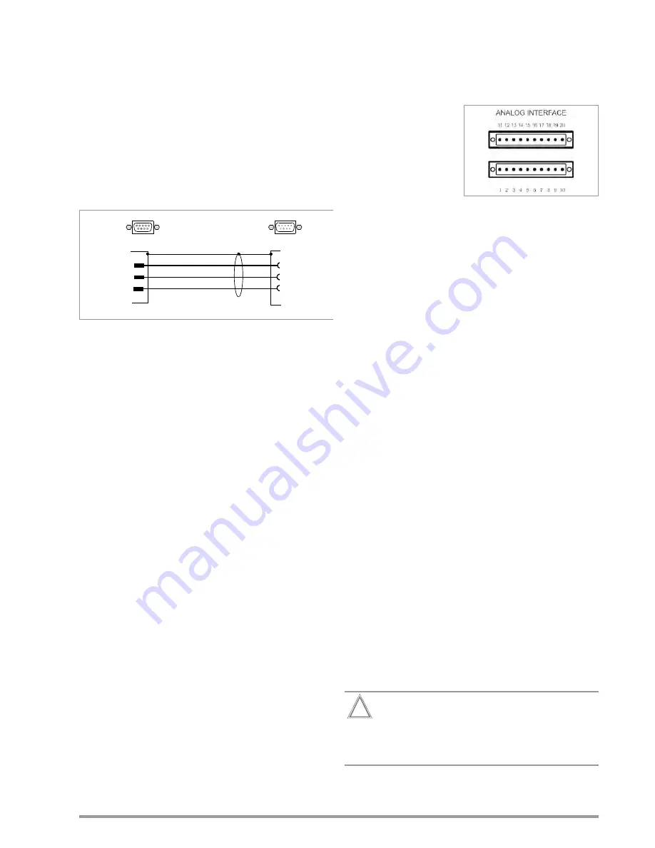
RS 232C Interface:
9-pin subminiature socket connector
DIN 41652
Connector pin assignments
Pin 2: TXD (transmit data)
Pin 3: RXD (receive data)
Pin 5: GND (ground)
Figure 1:Connector Cable for Serial Interface
c)
GPIB or IEC Bus Interface (optional)
This interface is optional and can be installed to the slot
provided for this purpose on the rear panel.
IEEE 488/IEC 625 Interface Connection
24-pin IEEE 488 socket connector
IEEE 488/IEC 625 Interface Functions
SH1
– SOURCE HANDSHAKE
AH1
– ACCEPTOR HANDSHAKE
T6
– TALKER
L4
– LISTENER
TE0
No extended talker function
LE0
No extended listener function
SR1
– SERVICE REQUEST
RL1
– REMOTE / LOCAL
DC1
– DEVICE CLEAR
PP1
– PARALLEL POLL
DT1
– DEVICE TRIGGER
C0
– No controller function
E1 / 2
– Open collector driver
Codes / formats
Per IEEE 488.2
2.3.7
Driver update (USB device driver)
We recommend a driver update in the following cases:
•
Replacement purchases of devices
(connecting new devices of the SYSKON range with a PC)
•
retrofitting of interface cards
•
firmware udate
•
software update
GMC-I Driver Control software can be downloaded from Gossen
Metrawatt's website at:
http://www.gossenmetrawatt.com
Produkte
Software
Software for Testers
Dienstprogramme
Driver Control
The ZIP file can be unpacked in any desired directory. The setup
file then appears in the directory. Installation is started by double
clicking the setup file. A wizard guides you through the installation
procedure.
2.3.8
Connecting the Analog Interface
The plug connection for the
analog interface is located on
the rear panel. Two 10-pin
plug-in screw terminal con-
nections are used to this
end. The necessary connec-
tions for the selected analog
control function can be made
here. In order to keep cross
interference with the analog
signals to a minimum, it is advisable to use shielded connector
cables. The individual signals are described under “Analog Inter-
face”.
2.4
Switching the Device On
After the described preparations have been completed, the
device can be switched on. The mains switch is located at the
bottom left-hand side of the front panel.
Start-Up Routine
After switching the device on, the POWER lamp [4] lights up and
the fan is started. The microprocessor included in the device then
starts a power-up test. The following operations are performed
during the test routine (duration approximately 6 seconds):
•
Reset all functional units (except battery-backed configuration
memory)
•
LED and display segment test
•
Hardware/firmware version display, see chapter 2.4.1
•
Line voltage range is detected, see chapter 2.4.2
•
Initialization of the 2 (possibly 3) computer interfaces; if the
device has been equipped with the optional “IEEE 488
interface”, the selected IEC bus device address then appears
briefly at the display (example: “Addr 12”).
See chapter 6 main menu level
SETUP DISPLAY & INTERFACE
for
changing the device address.
•
Date display (internal clock)
•
Time display (internal clock)
•
Recall last settings if applicable
•
Switch to (default after “*RST”) display of measured values for
voltage (Uout) and current (Iout)
After initial power-up, the device is set to its basic default
configuration (see the table entitled “Adjustable Functions and
Parameters” in chapter 10.1).
Upon shipment from the factory, the device is configured such
that the setpoints for output voltage and current are set to zero,
and the power output is set to off.
For further use, status after power on depends upon the selected
device configuration.
This configuration is selected either manually with the help of
the corresponding menu item, or by means of the POWER_ON
command.
Attention!
!
Avoid switching the device on and off in a rapid,
repeated fashion. This temporarily impairs the
effectiveness of the inrush current limiting function,
and may result in a blown fuse.
TxD
2
3
5
RxD
GND
2 RxD
3 TxD
5 GND
SYSKON
RS 232
PC / Controller
9-Pin Subminiature Socket Connector
9-Pin Subminiature Plug Connector
Summary of Contents for P1500
Page 68: ...68 GMC I Messtechnik GmbH ...
Page 71: ...GMC I Messtechnik GmbH 71 ...


