background image

GMC-I Gossen-Metrawatt GmbH

75

GB

Battery Replacement

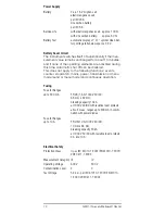
Lay the instrument onto a surface with the front panel 
facing down, loosen the two screws at the back and lift 
out the housing base starting at the bottom. The housing 
base and top are held together at the upper front side 
with the help of snap hooks.

Remove the battery from the batteries from the battery 
compartment.

Insert two 1.5 V mignon cells into the battery compart-
ment in the direction indicated by the polarity symbols.

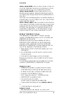
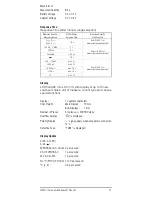
Important for reassembly: First set the housing base 
onto the housing top and align accurately (see photo 
below). Then press the two housing halves together, first 
at the bottom front (a), and then at the top front (b). 

Retighten the housing base with the two screws.

Please dispose of used batteries properly!

26.2

Power Pack

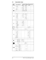
Use only the NA5/600 power pack from GMC-I Gossen-
Metrawatt GmbH for power supply to your instrument. The 
highly insulated cable assures safety for the operator, and 
the power pack provides for reliable electrical isolation 
(secondary rating: 5 V/600 mA). When a mains power 
pack is used, the batteries are switched off electronically 
and thus can be left inside the instrument. Please also 
observe the footnote

5)

 on page 65.

26.3

Fuses

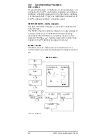
If at least one of the fuses blows, “FUSE” appears at the 
digital display, and an acoustic signal sounds at the same 
time.
The 10 A fuse interrupts the 3 A and 10 A ranges, and the 
1.6 A fuse all other current measuring ranges. All other 
measuring ranges continue to function.
If a fuse blows, eliminate the cause of the overload before 
placing the instrument back into operation!

Country

Type

Article number

Germany

NA5/600

Z218F

(b)

(a)

Summary of Contents for METRA HIT 28 S

Page 1: ...METRA HIT 28S METRA HIT 29S Precision Digital Multimeter 3 348 851 03 13 2 06 Operation Instructions ...

Page 2: ...ring range selection key Operating Mode Menu Individual menu item selection forward flux direction reduce values 5 ESC FUNC Multifunction key Operating Mode Menu Exit menu level and return to next highest level exit parameter entry mode without storage of values 6 Rotary switch for measurement functions 7 Connection jacks 8 Power pack connection jack 9 DKD calibration mark 1 2 3 4 5 6 7 7 max 600 ...

Page 3: ...ng 9 Reference value 10 Memory display hold measurement value 11 Stopwatch activated or elapsed time since start of measurement 12 Together with symbol 11 elapsed time since activation of corresponding function counter number of events when trigger threshold is exceeded 13 MIN MAX storage 14 Event marking 15 Synchronized storage METRA HIT 29S only 16 Memory mode METRA HIT 29S only 17 Manual measur...

Page 4: ...ternating Voltage Level Measurement dB 19 9 Current Measurement 21 9 1 Measurement with Clip On Current Transformers 22 9 1 1 Transformer Output mA or A for AC Measurements 22 9 1 2 Transformer Output V for AC and DC Measurements 23 10 Resistance Measurement 24 11 Continuity Testing for Resistance Measurement 25 12 Diode Testing 26 13 Continuity Testing for Diode Tests 27 14 Capacitance Measuremen...

Page 5: ...gger Function Parameters 52 23 Setting the Measurement Parameters 56 23 1 Description of General Parameters in the SEt Menu 58 23 1 1 Sampling Rate rAtE 58 23 1 2 Rapid Query MenuCYCLE 58 23 1 3 tiME und Datum dAtE 58 23 2 Parameter Description of Menu Item inFo 59 23 3 Default Settings 59 23 4 List of All Parameters 60 24 Data Transmission via the RS 232 Interface 61 24 1 Activating the Interface...

Page 6: ... It also prevents the switching of the rotary selector to disallowed functions when a measure ment cable is plugged into a socket Exception METRA HIT 29S in switch position W mA or W A jack V remains open for power measurement in position W A jack mA is only partially covered or blocked Use for Intended Purpose The multimeter described herein is a portable instrument which can be held in one hand ...

Page 7: ...anges are equipped with fuses Nominal volt age of fuse 1000 V The maximum allowable voltage for the measuring current circuit rated voltage of the fuse is equal to 600 V AC DC in the mA and A ranges In switch position AUTO SELECT Ω C and F the instru ment may only be used in power installations when the electri cal circuit is protected with a fuse or circuit breaker up to 20 A and the nominal volt...

Page 8: ... of a live open instru ment is required this may only be carried out by trained personnel who are familiar with the dangers involved Errors and Extraordinary Strains If it may be assumed that the instrument can no longer be operated safely it must be removed from service and secured against unintentional use Safe operation can no longer be relied upon if the instrument demonstrates visible damage ...

Page 9: ...e can cause incorrect displays and may block the measuring sequence To reset switch the instru ment off and then back on If this procedure is unsuccessful briefly disconnect the battery from the contact terminals Setting Time and Date See Chapter 23 1 3 page 58 Switching the Instrument Off Manually Press and hold the ON key until the display is deacti vated Deactivation of the instrument is acknow...

Page 10: ...ument to fre quency measurement events counting or count zero crossing The instrument is automatically switched to the next highest or next lowest measuring range for the follow ing measured quantities 1 2800 digits apply when switching from 300 kHz to 30 kHz 3 2 Manual Measuring Range Selection The automatic measuring range feature can be deactivated and the ranges can be manually selected and pr...

Page 11: ...ect deci mal point and sign The selected unit of measure and the current type are also displayed A minus sign appears in front of the number for the measurement of zero frequency direct quantities if the positive pole of the measured quan tity is applied to the input OL overload is displayed if the actual value falls below the measuring range lower limit for the following measured quantities V DC ...

Page 12: ...s At the same time MAN appears and indicates that the mea suring range is now set The test probes can now be removed from the measuring point and the measurement value can be read from the sub display If the measure ment value lies below the limit value shown in the table the instrument is reactivated for the storage of a new value the DATA display blinks Comparison of measurement values DATA Comp...

Page 13: ... 300 Ω or 3 nF Abbreviations MR Measuring range As long as the DATA function is active the measuring ranges should not be changed manually The DATA function is deactivated if the DATA CLEAR key is pressed and held approx 1 s if the rotary switch is acti vated or if the instrument is switched off and back on again Function DATA DATA Condition Response at Instrument Measuring Function Measurement Va...

Page 14: ... played MIN and MAX values are deleted by pressing and holding the DATA CLEAR key approx 1 s by activating the rotary switch or by switching the instrument off and back on again Note No new MIN MAX values are determined for 2 seconds after a change of measuring range so that measurement values can stabilize Function MIN MAX DATA MIN and MAX MeasurementValues Time of Measurement Reaction at Instrum...

Page 15: ...ief DATA brief DATA brief DATA brief MIN MAX tMIN MIN tMAX MAX Current DATA brief 09 20 05 09 20 05 015 000 015 345 015 345 015 345 015 986 015 123 015 345 015 678 015 986 Measurement Value Current Measurement Value Current Meas Value Current Meas Value ...

Page 16: ...T table on page 67 Note Diodes must be connected from the anode side pole to the jack For polarized capacitors the pole must be con nected to the F jack and the pole to the jack Resistors and semiconductor paths connected in parallel to the capacitor distort measurement results Set the rotary switch to AUTO SELECT Attention In the auto select function no more than 600 VTRMS may be applied between ...

Page 17: ...s 1000 V Attention Make absolutely certain that neither of the current ranges mA or A is active when the multimeter is connected for voltage measurements If the fuse trip limits are exceeded due to operator error both the operator and the instrument are in danger Zero Balancing in the 300 mV Measuring Range Select the 300 mV measuring range Connect the measurement cables to the instrument and conn...

Page 18: ... front time of 1 2 50 μs Due to the fact that overvoltages of greater duration can be expected for measurements at transform ers or motors etc we recommend our KS30 measuring adapter It provides protection against transient overvolt ages of up to 6 kV with a halftime value for front time of 10 1000 μs Continuous loading capability is equal to 1200 VTRMS Additional influence error due to use of the...

Page 19: ...upon the mea suring range 300 mV 600 V and is displayed The default setting for the reference level is 0 dB 0 775 V 1 mW at 600 Ω and appears in the left hand sub display This value can be changed in the Setup menu SEt V rEFvALUE V unit dB XXX XXX V dB VU Note No matching resistors have been installed into the instrument It takes measurements with a high input resistance of 5 MΩ Input resistance f...

Page 20: ... ESC FUNC and MAN AUTO keys are pressed simulta neously the actual measurement value becomes the ref erence value The instrument returns to the first display with the measurement value as reference level If the ESC FUNC multifunction key is activated repeatedly the instrument is switched to frequency measurement event measurement voltage measurement and finally back to level measurement The dB ran...

Page 21: ...ured quantity by briefly pressing the multifunc tion key ESC FUNC Each activation of the key causes alternate switching between DC and DC AC as well as acknowledgement by means of an acoustic signal The symbols DC and DC AC indicate the selected volt age type at the LCD display After the range has been selected with the rotary switch the DC current mode is always active If the multifunction key ES...

Page 22: ...rotected with a FF UR 10 A 1000 V AC DC fuse The breaking capacity of the fuse is equal to 30 kA at a nominal voltage of 1000 V AC DC with resistive load If one of the fuses has blown FUSE appears at the LCD and an acoustic signal occurs simultaneously when voltage has been applied If a fuse blows eliminate the cause of the overload before placing the instrument back into operation Fuse replacemen...

Page 23: ...and connect the transformer to the and mA or A jacks Note After measurement with the current clip has been com pleted oFF should be selected in the setup menu Incorrect measurement values will otherwise result in the mA A AC range because the transformation ratio is still being taken into consideration The maximum allowable operating voltage is equal to the rated voltage of the current transformer...

Page 24: ...onnect the free cable ends to one another Briefly press the multifunction key ESC FUNC The instrument acknowledges zero balancing with an acoustic signal and 000 000Ω and the ZERO symbol appear at the LCD The resistance which was measured at the moment the key was activated serves as a refer ence value max 20000 digits It is automatically sub tracted from subsequently measured values Zero balancin...

Page 25: ...r is switched on or prior to measurement function selection as this would lead to zero point adjust ment OL is displayed if the DUT is not connected Briefly press the multifunction key ESC FUNC Activation is acknowledged with an acoustic signal The symbol is simultaneously displayed at the LCD Connect the measurement cables to the DUT Deactivate continuity testing acoustic signal OFF Briefly press...

Page 26: ...e forward voltage in volts As long as the voltage drop does not exceed the maximum display value of 1 8 V you can test several ele ments connected in series or reference diodes with small reference voltages Reverse Direction or Interruption The measuring instrument indicates overflow OL Note Resistors and semiconductor paths connected in parallel to the diode distort measurement results See chapte...

Page 27: ...gnal ON Briefly press the multifunction key ESC FUNC Activation is acknowledged with an acoustic signal The symbol is simultaneously displayed at the LCD OL is displayed if the DUT is not connected Connect the measurement cables to the DUT Deactivate continuity testing acoustic signal OFF Briefly press the multifunction key ESC FUNC a second time Deactivation is acknowledged with an acoustic signa...

Page 28: ...c itance of the cables can be eliminated with zero balancing for the measurement of small capacitive values in the 3 nF and 30 nF ranges Connect the measurement cables to the instrument without a DUT Briefly press the multifunction key ESC FUNC The instrument acknowledges zero balancing with an acoustic signal and 0 000 and the ZERO symbol appear at the LCD The capacitance which was mea sured at t...

Page 29: ... display for V twice for V once The instrument switches to frequency measurement Frequency is read out to the main display and voltage amplitude to the left hand sub display The frequency measuring range can be selected subse quently The lowest measurable frequencies and maximum allow able voltages can be found in Chapter 25 Characteristic Values From the frequency measurement mode you can switch ...

Page 30: ... open connector jacks The instrument displays the measured temperature in the desired unit of measure Note The cable resistance entered in the Setup menu is automatically taken into consideration for this mea surement The default setting is 0 1 Ω 16 2 Temperature Measurement with Thermocouple and Reference Junction Enter the type of sensor to be used J or K in the Setup menu SEt V tEMPSEnSor VU J ...

Page 31: ...re in the desired unit of measure Note The internal reference temperature internal refer ence junction temperature is measured with a tem perature sensor in close proximity to the input jacks It is somewhat higher than room temperature due to internal warming The extent of this deviation has no influence on measuring accuracy Temperature Menu Symbol for Multimeter Flow Direction Key time Sensor K ...

Page 32: ... examples in the table below as well as Chapter 23 Set ting the Measurement Parameters SEt V triG V EVENTS H triG XXXXXX VU L triG XXXXXX VU Set the rotary switch to V or V Manually select the measuring range for event counting Apply the signal in the same fashion as for voltage mea surement Repeatedly press the multifunction key ESC FUNC until EVENTS appears at the display Example Entries for Tri...

Page 33: ...tart of events measurement ON Total time of all events voltage above H triG The DATA CLEAR key has no function in this case Recorded events are automatically deleted by switching to voltage measurement with the ESC FUNC key FUNC brief FUNC brief FUNC brief Total Time Number of Zero Crossings Overall Time 00 000 000 00 000000 000001 002 4 00 00 30 00 00 07 0 5000 of All Events ...

Page 34: ... measured with this function Set the rotary switch to V Select a measuring range between 3 V and 600 V with the MAN AUTO key Note This function cannot be activated in the 300 mV measuring range Press and hold the ESC FUNC key The clock is reset and 00 00 00 and the clock symbol are displayed at the LCD The clock can be started and stopped by pressing the MAN AUTO key Minutes seconds and tenths of ...

Page 35: ... brief DATA CLEAR long Activate Stopwatch Start Stopwatch Capture Intermediate Time Update Intermediate Time Stop the Clock Reset Stopwatch Exit Function 00 00 00 00 00 3 00 01 2 00 35 0 04 00 28 00 00 00 00 01 23 00 01 23 00 35 06 00 35 06 00 01 23 00 35 06 00 01 23 MAN AUTO MAN AUTO ...

Page 36: ...ng range manually In order to enter the Δ operating mode simultaneously press the ESC FUNC and MAN AUTO keys The current measurement value is then displayed normal ized in reference to the stored reference value Alternatively a measurement value can be assigned as a refer ence value by briefly pressing the ESC FUNC and the MAN AUTO keys simultaneously in the Δ mode This refer ence value remains ac...

Page 37: ...nges from 300 mV to 300 V 020 000 002 000 Measuring Range Effective Reference Value 300 mV 200 mV 20 mV 2 mV 3 V 2 V 200 mV 20 mV 30 V 20 V 2 V 200 mV 300 V 200 V 20 V 2 V 600 V 2 2 Values of up to 60000 digits are reasonable for the 600 V measuring range because this maximum value results in a reference value of 600 V which corresponds to the measuring range upper limit 200 V 20 V ...

Page 38: ...r 20 3 Set the rotary switch to W mA max 300 mA or W A max 10 A see page 70 Briefly press the ESC FUNC key Measurement is switched from A DC to A DC and AC Press the ESC FUNC key a second time to start active power measurement Each additional activation of the ESC FUNC key causes switching to the various display functions for active power W apparent power VA reactive power VAr energy Wh mean value...

Page 39: ... per measured time period FUNC brief e g 15 minutes maximum see EnErGY Elapsed time since start of energy measurement 115 00 115 50 001 50 215 000 116 00 230 0 0 500 230 0 0 500 1 00 00 60 00 14 37 06 05 06 98 Time Date FUNC brief Mean value during integral action time see EnErGY Elapsed time since start of a new time interval 120 000 00 10 00 mean Analog If measurement value 1 of smallest measuri...

Page 40: ...24 V the same trigger level triG cont in applies for High Low detection Other parameters to be configured pulse kWh ratio unit of mea sure W VA or VAr for mean and maximum values as well as the corresponding integral action time see chapter 20 3 Set the selector switch to Press the ESC FUNC key twice Active power measurement has now been activated Each additional activation of the ESC FUNC key cau...

Page 41: ... demand time 00 15 3 30 V W VA VAr Pulses W VA VAr demand time 00 60 W VA W V W In memory mode measurement values for P W I A and V V are always stored to memory at the selected rAtE independent of displayed power quantities see Chapter 23 1 3 page 58 In memory mode only the mean value generated at the interval selected under dEMAnd tiME in hh mm for the selected power quantity dEMAnd unit W VA VA...

Page 42: ...he power measurement mode 20 5 Power Measurement with Clip On Current Transformers Only current transformers with mA or A output can be used Since DC current clips are only equipped with one voltage output measurement of DC power with clips is not possible Chapter 9 1 1 page 22 contains information for taking transformation ratios into consideration 600V V F C A mA 10A 300mA N L 300 mA 10 A ...

Page 43: ...ust be entered in the setup menu before measurement is started if these have not already been set see chapter 23 Set the rotary switch to V Repeatedly press the ESC FUNC key until StorEd is dis played immediately follows EVENTS display Basic Display As soon as the multimeter records an event the type of fault is first read out to the sub display which is followed by the display StorEd At the same ...

Page 44: ...and number of Event 4 lower limit violation Event 3 upper limit violation Event 2 drop out Event 1 pulse or short duration peak 233 03 L0 Hi drp out PuLse StorEd 000004 01 15 01 00 02 06 03 35 06 02 48 06 000004 000003 000002 000001 Esc 000001 00 00 07 231 33 i i i registered events ...

Page 45: ... possible in Display 2 with the VU keys Display 2 is exited by pressing the ESC FUNC key and the instrument is returned to the basic display Note The functions ZERO DATA MIN MAX and DELTA are disabled in the line fault recording mode Deleting Events All stored events can be deleted by simultaneously activat ing the MAN AUTO and DATA CLEAR keys Basic Display current measurement value Display 1 lowe...

Page 46: ...t should always be greater than the respec tive lower limit Entering upper and lower thresholds in digits SEt V triG V MAinS rAnGE XXXX V e g 600 V H triG XXXXXX VU e g 250000 250 00 V L triG XXXXXX VU e g 190000 190 00 V Examples for the entry of trigger thresholds in digits can be found in the table in Chapter 17 1 page 32 Drop Out Trigger Level triG drPout A level with a value ranging from 0 V ...

Page 47: ...00 000 measurement values minimal signal deviation rate 0 5 s hysteresis ALL The mea surement data are stored as so called data blocks Mea surement values from the same measuring function are stored in the same block Data are acquired relative to real time Thus the instrument may also be used as a real time data logger Only absolute values and absolute time records can be stored no relative or Δ v...

Page 48: ...ndividual storage events such as the stor age of measurement values are indicated by a brief disap pearance of the MEM display As long as the storage rate is less than 1 s MEM blinks once per second TRIG Display The TRIG symbol indicates that a trigger event has occurred A blinking TRIG symbol indicates that the trigger has been activated and that it is waiting for a trigger event to occur SAMPLE ...

Page 49: ...sly at the main display the decimal point is fixed automatic measuring range selection is disabled StorE buSY appears at the sub displays each measurement value is stored to memory trigger and hysteresis are not active Toroidal core memory mode is deactivated CYCLErAM OFF see chapter 22 1 Menu Mode Main Menu Store Current Memory Occupancy SEt Store StorE ESC 00 00 01 60 ESC 2x 015 000 ...

Page 50: ...n saved to memory The entire RAM can be cleared which contains for exam ple power disturbance data SEt V rAM no V YES 22 1 General Parameters Memory Duration durA This parameter allows for a determination as to whether or not measurement values should only be stored for a limited amount of time If memory duration is activated on a period of time during which data are to remain in storage can be en...

Page 51: ...le for real time analysis at a PC with simultaneous display at the monitor See chapter 23 for entering the Operating Mode Menu Enter hysteresis as follows SEt V HYSt 000500 UV 22 2 Trigger Functions With the help of the trigger functions except for trigger events trigger cont in and mains trig hi lo you can determine which measurement values are stored to mem ory In the following examples for the ...

Page 52: ...er Limit H triG Lower Limit L triG Each trigger function is assigned its own upper and lower limits as trigger parameters The upper limit should be greater than the respective lower limit The predetermined trigger threshold is evaluated according to the selected measuring range independent of whether or not automatic measuring range selection is activated Entering upper and lower trigger threshold...

Page 53: ...drPout XXXX V triG PULSE XXXX V PrEtr OFF on rEtriG OFF on VU Note We recommend the entry of a defined memory duration prior to activation of the re trigger see Memory Duration durA on page 50 Time Trigger tiME triG dAtE trig If this function has been activated and if the memory mode is on measurement values are only stored as of the specific point in time after which current date and time agree w...

Page 54: ... time trig off pretr off trig 0ff trig sto out trig sto in trig in trig out date trig 00 00 00 time trig 00 00 00 pretr on time trig on time off retrig on time trig off date trig on h trig 000000 V set trig L trig 000000 V set Trigger Menu ...

Page 55: ...nge 300 1000 V h trig mains 100000 V trig drpout 0 1000 V trig pulse 200 1000 V trig contin trig contin Ω V trig contin 0 999ΩImV trig EVENTS h trig 000000 V l trig 000000 V Symbol for Multimeter Flow Direction Key L trig mains 000000 V trig mains ...

Page 56: ... corresponding parameter in the sub menu After the characters or the unit of measure have been selected the instrument is returned to the menu mode SEt with the key Return to the measuring mode by pressing and holding the ESC FUNC key until the measuring display appears In order to switch the multimeter off press and hold the ON key until the display goes blank Examples Battery Voltage Query SEt i...

Page 57: ...nSor tEMPunit rEFvALUE EnErGY dEMAndunit time Addr MEnuCYCLE tiME OCCUP tEStrAM bAtt noSurE YESSurE SEt inFo on OFF Sub Menus Main menu SEt is active menu mode SEnd SEt inFo SEnd rAMCLEAR SEt inFo SEnd rAM StorE Main Menus METRA HIT 28S Main Menus METRA HIT 29S Parameters in Bold Typeface METRA HIT 29S only MENU ENTER ...

Page 58: ...ay and by an acoustic signal Storage is done in the same data block as long as the measuring function is not changed dAtA This setting provides for transmission of the measurement values from the multimeter to the interface or storage of these values which have been generated in the measure ment value storage function DATA Setting the Sampling Rate SEt V rAtE s zht mm ss VU t thousandths of a seco...

Page 59: ...subsequently read out If the test is completed successfully PASSEd appears at the display Significance of possible messages bUSY RAM test is running PASSEd Test successfully completed Err1 Test sample for this test is faulty Err2 Test sample for a previous test is faulty If Err1 and or Err2 occur a hardware problem may exist Send the multimeter to our Repair and Replacement Parts Service Departmen...

Page 60: ...YSt 51 Hysteresis HYSt L triG 32 Example Entries for Trigger Thresholds L triG 46 Trigger Thresholds H triG and L triG 52 Upper Limit H triG Lower Limit L triG MAinS rAnGE 46 Mains Failure Measuring Range MAinS rAnGE MEnuCYCLE 58 Rapid Query MenuCYCLE ModEM 62 ModEM Modem PrEtr 52 Pre Trigger PrEtr OCCUP 50 Memory Occupancy Query OCCUP rAMCLEAR 50 rAMCLEAR Delete Memory rAtE 58 Sampling Rate rAtE ...

Page 61: ... instrument to the PC via the interface adapter The interface is activated automatically for the receipt of data downloading from the PC to the instrument as soon as transmission is started at the PC Starting Transmission Mode Operation via Menu Functions SEt V SEnd OFF V on Starting Transmission Mode Operation via Shortcut With the instrument switched off press and hold the DATA CLEAR key and the...

Page 62: ...erface adapter in use must be selected for this parameter The SI232 II memory adapter allows for on site storage of measurement values for METRA HIT 28S measuring instrument The SI 232StorE operating mode must be selected SI 232onLinE must be selected for online trans mission to the PC without storage to memory ModEM Modem Indication must be made here as to whether or not a modem has been connecte...

Page 63: ... a WINDOWS full version and is compatible with WINDOWS 95 98 and NT Measurement data from several METRA HIT 28S or METRA HIT 29S multimeters can be simultaneously acquired stored represented and documented with METRAwin 10 METRAHit software Measurement val ues can be displayed in the following formats digital display similar to multimeter display up to four multimeters as a characteristic curve XY...

Page 64: ...A 10 nA 100 nA 20 mA 30 mA 100 nA 1 μA 300 mA 1 μA 10 μA 3 A 100 μA 10 A 1 mA Ω 300 Ω 1 mΩ 3 kΩ 10 mΩ 30 kΩ 100 mΩ 300 kΩ 1 Ω 3MΩ 4 5 10 Ω 30MΩ 4 5 100 Ω Ω 300 Ω 0 1 Ω 300 mV 100 μV 3 V 100 μV F 3nF 5 1 pF 30 nF 10 pF 300 nF 100 pF 3 μF 1 nF 30 μF 10 nF 300 μF 100 nF 3000 μF 1 μF 30000 μF 1 μF Hz 300 000 Hz 0 001 Hz 3 00000 kHz 0 01 Hz 300 000 kHz 1 Hz 100 min 2 100 ms 1 10 s C F Pt 100 Pt 1000 20...

Page 65: ...esults Meas Function Measuring Range Input Impedance V 300 mV 20MΩ 5 MΩ 50 pF 3 V 11MΩ 5 MΩ 50 pF 30 V 10MΩ 5 MΩ 50 pF 300 V 10MΩ 5 MΩ 50 pF 600 V 10MΩ 5 MΩ 50 pF dB see table on page 67 same as V Approx Voltage Drop at Meas Range Upper Limit A 300 μA 160 mV 160 mV 3 mA 160 mV 160 mV 20 mA 30 mA 170 mV 170 mV 300 mA 300 mV 300 mV 3 A 110 mV 110 mV 10 A 350 mV 350 mV Open Circuit Voltage Meas Curre...

Page 66: ...0 01 5 0 5 30 3 A 0 2 0 05 5 0 7 30 15 10 A 9 continuous 10 A 0 2 0 05 5 0 5 30 rdg r d 300 Ω 0 05 0 01 5 10 600 V DC AC TRMS sine 10 min 3 kΩ 0 05 0 01 5 10 30 kΩ 0 05 0 01 5 300 kΩ 0 05 0 02 5 3MΩ 0 1 0 02 5 30MΩ 1 0 2 5 Ω 1 0 3 0 2 0 3 3 V 0 2 0 3 rdg r 3 nF 1 0 0 2 10 600 V DC AC TRMS sine 10 min 30 nF 1 0 0 2 10 300 nF 1 0 0 2 3 μF 1 0 0 2 30 μF 1 0 0 2 300 μF 5 0 1 3 mF 5 0 1 30 mF 5 0 1 rdg...

Page 67: ...13 Without integrated reference junction with integrated reference junction additional error 2 K 14 For V 10 of the measuring range 15 valid as from 500 digits Abbreviations rdg Reading r Measuring range d Digit Measuring Range Display Range Reference Voltage V 0 775 V Resolution 300mV 3V 30V 300V 600V 48 dB 8 dB 38 dB 12dB 18 dB 32 dB 2 dB 52 dB 22 dB 63 dB 0 01 dB 0 01 dB 0 01 dB 0 01 dB 0 01 dB...

Page 68: ... Frequency Influence Range max Resol Influence Effect 2 rdg Frequency VAC 15 Hz 45 Hz 300 000 mV 2 10 d 65 Hz 1 kHz 0 5 1kHz 10 kHz 1 10kHz 50 kHz 3 50kHz 100 kHz 10 15 Hz 45 Hz 3 00000 V 30 0000 V 300 000 V 2 10 d 65 Hz 1 kHz 0 5 1kHz 20 kHz 1 5 20kHz 100 kHz 5 15 Hz 45 Hz 600 00 V 2 10 d 65 Hz 1 kHz 1 1kHz 10 kHz 10 Influence Variable Frequency Meas Quantity Measuring Range Influence Effect 2 rd...

Page 69: ... Variable Influence Range Measuring Range Damping dB Common Mode Interference Voltage Interference quantity max 600 V V 90 dB Interference quantity max 600 V 50 Hz 60 Hz sine 300 mV 30 V 80 dB 300 V 70 dB 600 V 60 dB Series Mode Interference Voltage Interference quantity V resp measuring range nominal value max 600 V 50 Hz 60 Hz sine V 60 dB Interference quantity max 600 V V 60 dB 1 2 3 4 5 CF 0 1...

Page 70: ...ration W VAr VA 1 mW 0 1 μW V 600 V mA 0 36 A A 10 A DC AC TRMS sine V mA continuous 10 A cont 12 A 5 min 16 A 30 s 10 mW 1 μW 100 mW 10 μW 1 W 0 1 mW 10 W 1 mW 100 W 10 mW 1 kW 0 1 W 10 kW 1 W Meas Quantity Meas Range Intrinsic Error of rdg d 15 Hz 45 Hz 45 Hz 65 Hz 65 Hz 1 kHz Active Power 300 mA 10 A 1 3 20 1 20 3 20 Reactive Power 2 5 20 1 5 20 3 20 Apparent Power 1 2 20 1 20 1 2 20 Power Fact...

Page 71: ...L is displayed Polarity Display sign appears when plus pole is connected to Defective Fuse FUSE is displayed Display Update V DC AC DC A Ω EVENTS AC DC Count 2 per second V AC EVENTS AC 1 per second W VA VAr Wh 1 per second Hz C Pt100 Pt1000 1 to 2 per second C J K 0 5 per second Measured Quantity Measuring Range Digital Display Response Time Measured Quantity Step Function V V A A 1 5 s from 0 to...

Page 72: ... This does not apply to the following functions events counter stopwatch mains power transmission or menu mode send or menu mode and continuous operation Fusing Fuse for Ranges up to 300 mA FF UR 1 6 A 1000 V AC DC 6 3 mm x 32 mm breaking capacity 10 kA at 1000 V AC DC with resistive load protects all curr meas ranges up to 300 mA in combi nation with power diodes Fuse for Ranges up to 10 A FF UR ...

Page 73: ...le baud rates BD232 USB HIT 9600 bauds Ambient Conditions Operating Temperature Range 20 C 50 C Storage Temperature Range 25 C 70 C without batteries Relative Humidity max 75 no condensation Elevation to 2000 m Deployment indoors outdoors only in the specified ambient conditions Mechanical Design Dimensions 84 mm x 195 mm x 35 mm Weight METRA HIT 28S approx 350 g with batteries METRA HIT 29S appro...

Page 74: ...C with the help of METRAwin 10 METRAHit software before replacing the battery in order to prevent data loss Operating parameters remain in memory although date and time must be reset You can check current battery condition in the Info menu SEt V inFo V bAtt X X V Before initial start up or after storage of your instrument make sure that no leakage has occurred at the instrument battery Repeat this...

Page 75: ...the two screws Please dispose of used batteries properly 26 2 Power Pack Use only the NA5 600 power pack from GMC I Gossen Metrawatt GmbH for power supply to your instrument The highly insulated cable assures safety for the operator and the power pack provides for reliable electrical isolation secondary rating 5 V 600 mA When a mains power pack is used the batteries are switched off electronically...

Page 76: ...t is a category 9 product monitoring and control instrument in accordance with ElektroG German Electrical and Electronic Device Law This device is not subject to the RoHS directive We identify our electrical and electronic devices as of August 2005 in accordance with WEEE 2002 96 EG and ElektroG with the symbol shown to the right per DIN EN 50419 These devices may not be disposed with the trash Pl...

Page 77: ...ty Maximum Rated Voltage Measuring Category 1000 V CAT III 600 V CAT IV Maximum Rated Current 16 A Ambient Conditions EN 61010 031 Temperature 20 C 50 C Relative Humidity 50 80 Pollution Degree 2 29 Repair and Replacement Parts Service DKD Calibration Lab and Rental Instrument Service If service is required please contact GMC I Gossen Metrawatt GmbH Service Center Thomas Mann Strasse 20 90471 Nürn...

Page 78: ...alibration certificates Our spectrum of offerings is rounded out with free test equipment management An on site DKD calibration station is an integral part of our service department If errors are discovered during calibra tion our specialized personnel are capable of completing repairs using original replacement parts As a full service calibration laboratory we can calibrate instruments from other...

Page 79: ...49 911 86 02 112 Fax 49 911 86 02 709 E Mail support gossenmetrawatt com DKD Calibration Certificate Reprints If you order a DKD calibration certificate reprint for your instrument please provide us with the reference number indicated in the upper and lower most fields of the calibra tion mark We do not need the instrument s serial number ...

Page 80: ...nge without notice A pdf version is available on the internet GMC I Gossen Metrawatt GmbH Thomas Mann Str 16 20 90471 Nürnberg Germany Phone 49 0 911 8602 0 Fax 49 0 911 8602 669 E Mail info gossenmetrawatt com www gossenmetrawatt com ...

Reviews: