26
GMC-I Gossen-Metrawatt GmbH
12
Diode Testing
➭
Be certain that the device under test is voltage-free.
Extraneous voltages distort the measurement results!
➭
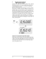
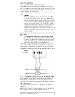
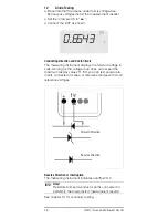
Set the rotary switch to“
”.
➭
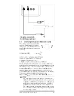
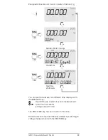
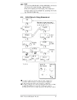
Connect the DUT as shown.
Conducting Direction and Short-Circuit
The measuring instrument displays the forward voltage in
volts. As long as the voltage drop does not exceed the
maximum display value of 1.8 V, you can test several ele-
ments connected in series, or reference diodes with small
reference voltages.
Reverse Direction or Interruption
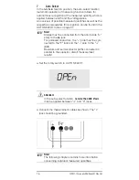
The measuring instrument indicates overflow “OL”.
Note!
☞
Resistors and semiconductor paths connected in
parallel to the diode distort measurement results!
See chapter 13 for continuity testing.
0
.
6543
Forward Direction
Reverse Direction
600V
V
F
°
C

