OM--05096
S SERIES
MAINTENANCE & REPAIR
PAGE E -- 2
SECTION DRAWING
A
B
C
D E
F
G
H
J
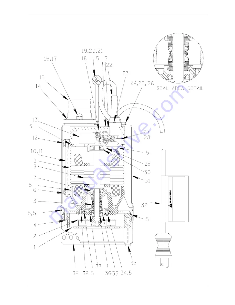
Figure 1. Pump Model S1 1/2C3---E.33 115/1
Page 1: ...PANY F MANSFIELD OHIO GORMAN RUPP OF CANADA LIMITED D ST THOMAS ONTARIO CANADA Printed in U S A ECopyright by the Gorman Rupp Company INSTALLATION OPERATION AND MAINTENANCE MANUAL WITH PARTS LIST SUBM...
Page 2: ...rage and Cold Weather Preservation PAGE C 2 TROUBLESHOOTING SECTION D PAGE D 1 PUMP MAINTENANCE AND REPAIR SECTION E PAGE E 1 PERFORMANCE CURVE PAGE E 1 PARTS LISTS S1 1 2C3 E 33 115 1 Pump Model PAGE...
Page 3: ...n Rupp distributor or write The Gorman Rupp Company or Gorman Rupp of Canada Limited P O Box 1217 70 Burwell Road Mansfield Ohio 44901 1217 St Thomas Ontario N5P 3R7 The following are used to alert ma...
Page 4: ...attempt to pump any liquids which may damage the pump or endanger personnel as a result of pump failure Never attempt to alter the length or re pair any power cable with a splice The pump motor and c...
Page 5: ...nspect the pump assembly for cracks dents damaged threads and other obvious dam age b Check for and tighten loose attaching hard ware c The pump is furnished with a 30 foot 9 meter long power cable In...
Page 6: ...for general contracting applications Each pump weighs approximately 28 lbs 13 kg The weight does not include the discharge piping Attach a rope or chain to the lifting handle on the top of the pump D...
Page 7: ...pport the pump by the handle on the pump If the bottom is heavily sludge covered rest the pump on support blocks or suspend it near the surface of the liquid If the application involvesa lot of debris...
Page 8: ...ion For maximum pumping capacity use non collaps ible hose or rigid piping and keep the discharge as short and straight as possible If rigid piping is used minimize the use of elbowsand fittingswhich...
Page 9: ...ons Never attempt to alter the length or re pair any power cable with a splice The pump motor and cable must be com pletely waterproof Damage to the pump or personal injury may result from alter ation...
Page 10: ...pressure into the pump casing or piping to remove a blockage This could result in personal injury or damage to the equipment If backflushing is absolutely neces sary liquid pressure must be limited t...
Page 11: ...wed or submerge it into the liquid If the liquid is near freezing the pump must be sub merged for an extended period of time Start the pump and check for shaft rotation If still frozen al low addition...
Page 12: ...om of rotation Add shims or gaskets as required Liquid level device s fouled with mud Clean liquid level device s or foreign material Float type sensing device s tangled or Check installation for free...
Page 13: ...THE PUMP WILL MAINTAIN PEAK OPERATING PERFORMANCE STANDARD PERFORMANCE FOR PUMP MODELS S1 1 2C3 E 33 115 1 and S2J3 E 5 115 1 Based on 70_ F 21_ C clear water at sea level Since pump installations ar...
Page 14: ...OM 05096 S SERIES MAINTENANCE REPAIR PAGE E 2 SECTION DRAWING A B C D E F G H J Figure 1 Pump Model S1 1 2C3 E 33 115 1...
Page 15: ...W CASING 26816 604 1 10 HOLDING ROD 26816 631 4 11 LOCKWASHER 26816 638 4 12 PUMP TOP COVER 26816 614 1 13 CAPACITOR 26816 613 1 14 DISCH FLANGE ASSY 26816 609 1 15 DISCH NIPPLE MNPT 26816 622 1 16 L...
Page 16: ...OM 05096 S SERIES MAINTENANCE REPAIR PAGE E 4 SECTION DRAWING A B C D E F G H J Figure 2 Pump Model S2J3 E 5 115 1...
Page 17: ...CASING 26816 704 1 10 HOLDING ROD 26816 631 4 11 LOCKWASHER 26816 638 4 12 PUMP TOP COVER 26816 614 1 13 CAPACITOR 26816 713 1 14 DISCH FLANGE ASSY 26816 509 1 15 DISCH NIPPLE MNPT 26816 022 1 16 LOC...
Page 18: ...elec trician to service the electrical compo nents of this pump Check the chart in TROUBLESHOOTING Section D to determine the nature of the pump problem If the problem is mechanical in nature such as...
Page 19: ...ete disassembly procedures for the pump motor are not included in this manual Instructions are provided only for replacement of the pump end components the power cable and capacitor If the pump fails...
Page 20: ...ious injury or death to personnel Carefully fold the capacitor and power cable leads under the motor top cover and secure the cover to the upper motor cover with the holding rods and lockwashers 10 an...
Page 21: ...SEAT SPRING BELLOWS UPPER SEAL RETAINER LOWER STATIONARY SEAT LOWER STATIONARY ELEMENT LOWER SEAL BELLOWS SPRING RETAINER ROTATING ELEMENT UPPER STATIONARY ELEMENT Figure 3 Seal Assemblies Seal Instal...
Page 22: ...aces contact Install the machine screws 38 and tighten them in an alternating pattern until the seal springs are compressed and the cover seats tightly against the gasket Fill the seal chamber with ap...
Page 23: ...d from the factory the pump seal cav ity was fully lubricated with Shell Turbo T68 oil Use only Shell Turbo T68 or Gulf Harmony HVI AW 26 oil for repair Quantities for each pump are as follows Seal Ca...
Page 24: ...rpumps com warranty or call U S 419 755 1280 International 1 419 755 1352 For Canadian Warranty Information Please Visit www grcanada com warranty or call 519 631 2870 THE GORMAN RUPP COMPANY D MANSFI...