


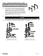


STEP 7 - FINAL STEPS
7.1
Verify all end stops are installed.
7.2
Check to make sure all bolts are tightened to specifications and lockwashers are flat.
7.3
If necessary, touch up system with paint provided.
7.4
Install yellow rubber tracdoms on steel runway ends.
7.5
Keep Packing List, Installation Manual and General Arrangement Drawing together and
file in safe place.
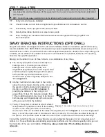
SWAY BRACING INSTRUCTIONS (OPTIONAL)
Support assemblies are designed to AISC (American Institute of Steel Construction) specifications using
recommendations from ANSI Z359.6. A fall event may cause longitudinal and lateral movement up to the
OSHA limit of 2 inches. If reduced movement of the support assemblies is desired, then sway bracing (not
included) can be added. The installer or end user must determine the possible locations of the bracing
based on the specific application.
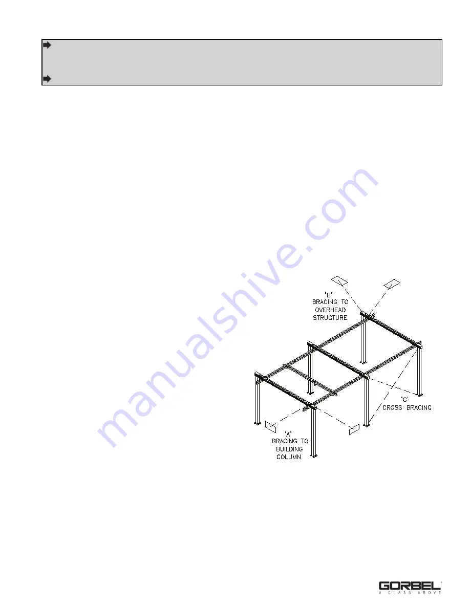
Bracing can be added in one of three formats, or a combination of any three.
A) The most typical place to brace is directly to a
building column. Providing a brace from a
building column to the lateral (side) and
longitudinal (lengthwise) axis of the support steel
provides extreme rigidity throughout the system,
and requires only minimal locations (2 or 3
corners of the system is typically adequate, see
‘A’
in
diagram 1
).
B) Another method is to brace back to the ceiling
above the crane. Again, bracing at the corners of
the system in both a lateral and longitudinal
direction is sufficient (see
‘B’
in
diagram 1
),
providing the distance to the ceiling is not
greater than 10 feet. For distances greater than
10 feet, additional points may need to be braced
both laterally and longitudinally at the discretion
of the end user and/or the installer.
C) Finally, if the system is located at a point where it
is not practical or possible to brace to the building
columns or the ceiling structure, cross bracing
can be done. This can be added to the sides of the system (see
‘C’
in
diagram 1
) to control longitudinal
sway, or across the open ends to limit lateral motion (not shown). This can also be added to the top of
the system, but should be check to make sure that it does not interfere with the travel of the bridge.
It should be noted that the use of sway bracing is purely subjective because it is not a requirement of
Gorbel, Inc. No specifications exist detailing appropriate methods, and the ultimate quantity and type is at
the discretion of the user and installer.
If bracing, always determine if the building structure is
adequate.
11
9/18 Rev C
IMPORTANT:
Do not throw away this manual: the manual provides critical instructions on the safe
use, inspection and maintenance of this equipment. Every user is required to read and understand
this manual.
TIP:
Do not throw away packing list: can be referenced for spare parts at a later date if required.
Diagram 1.
Examples of typical sway bracing locations.


