GORBEL Tether Track Installation, Operation & Maintenance Manual Download Page 19

INSPECTION AND MAINTENANCE SCHEDULE

GORBEL® TETHER TRACK® FREE STANDING BRIDGE AND MONORAIL ANCHOR 

SYSTEMS: INSPECTION AFTER A FALL ARREST EVENT

Free Standing Supporting Structure

•  Inspect foundation for any signs of damage or cracking. Repair as required.

•  Inspect column weldment connections to foundations. Check torque requirements per anchor bolt

manufacturer’s instructions (typically applying 20% of installed torque value is sufficient to determine if 

anchor bolt is loose).

•  Inspect column weldment and header weldment for any visual cracking in welds and/or any permanent

deformation. Repair as required.

•  Verify column to header hardware is tightened to 95 ft.-lbs. of torque per nut.

Runway/Monorail/Bridge


•  Support each Tether Track® section by other means and loosen all support hardware (splice


joint, spine clamp angle, truss splice plate, clamped endtruck and sway braces). This will


relieve any stress and misalignment in the anchor system members that may be retained by


the hardware from the arresting force. Any misalignment caused by hardware/member shift


must be removed before the track sections can be measured for permanent deformation.


•  Ensure all fitments and track sections are aligned. Re-tighten hardware on all components


per installation instructions in this manual.


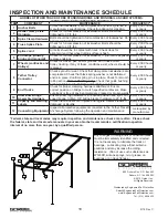
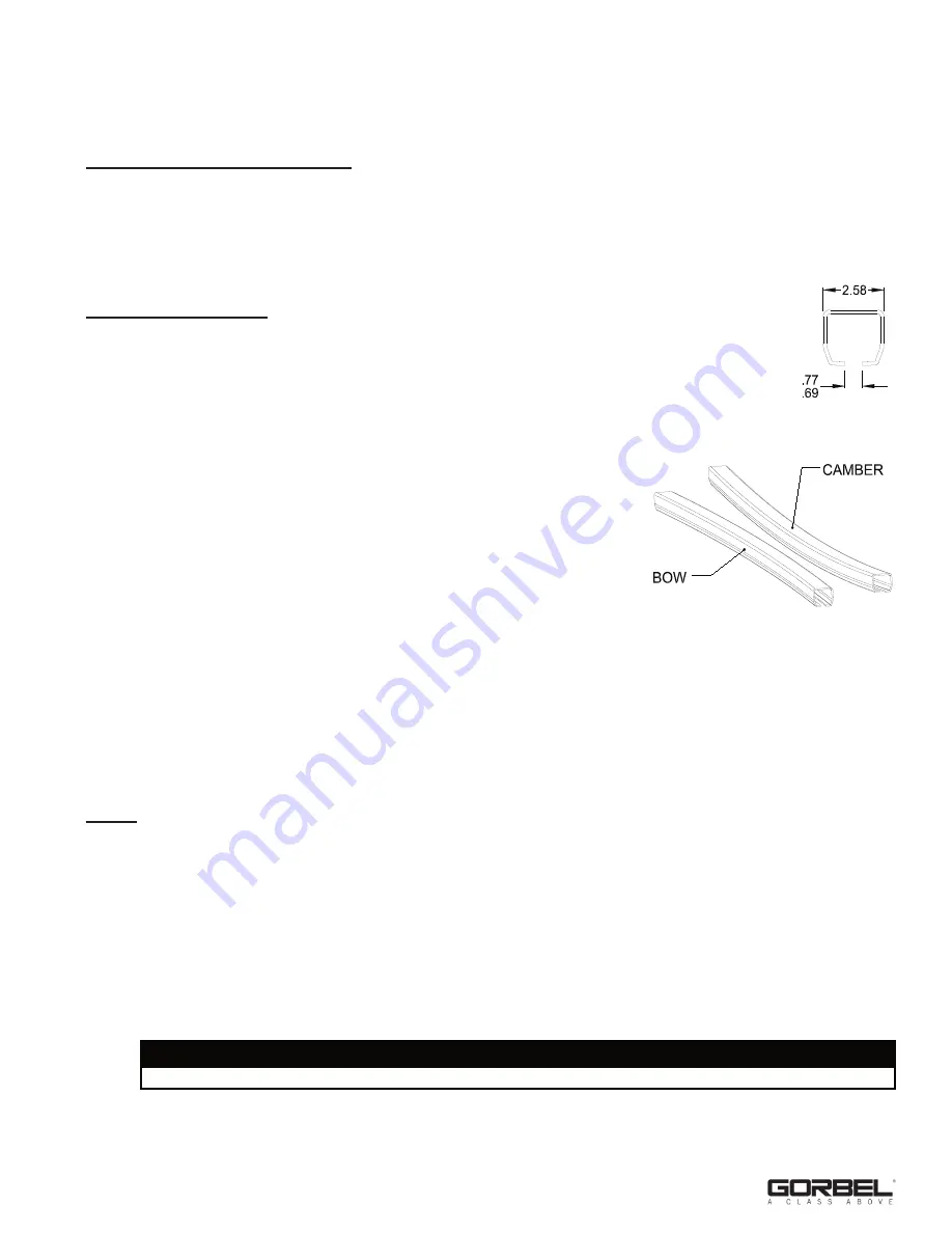
•  At the location in the track where the fall arrest incident took place,


measure the track opening and compare to the dimension and


tolerance shown in 

Diagram A

. Replace section of track if


measurement is not within the tolerance.


•  Verify the Tether Track® members have not undergone any other


permanent deformation. This can be achieved by measuring the


camber and bow (

Diagram B

) of the enclosed track member and top


tube member (if trussed track).


•  Using a string (kite), two clamps, and a measuring device (ruler,


tape measure, etc.), measure from support to support (covering


track area where arrest took place).


•  Clamp one end of string to the concave face of track, at the support. Travel to the other support


pulling the string taut, not allowing it to sag, and clamp it in same location on track at the support.


•  Measure the distance from the string to the track face where this distance is greatest (usually at mid-span).


•  If this measurement is greater than .125” X Length of track in feet between supports / 10’ then


replacement of track section is required.


•  Repeat this for both bow and camber of both the enclosed track member and top tube member (if trussed).

   • If arrest took place on cantilevered portion of track, measurement will be from end of track to first support.


•  Visually inspect endstops for fractures or deformation, replace if any are found.

Trolley


•  Roll trolley in track listening for abnormal thumping noise. If heard, this indicates there maybe debris sticking


to wheel(s) or a flat spot on wheel(s) and wheel replacement is required.


•  Remove endstop and carefully remove trolley from track section, install endstop bolt back into hole for safety

  purposes.


•  Inspect trolley wheels for debris, clean off if any debris is found with clean dry cloth.


•  Inspect black polyurethane washer between bolt head and metal washer for deformity. If bolt head is wedged


into washer, press up on eyebolt while pulling down with hands until black washer and bolt head have


separated. Verify eyebolt freely swivels.


•  Further, visually inspect trolley wheels for flat spots and/or fractures. If any are found, specific wheel


replacement is necessary.


•  Place trolley back into track and secure with endstop and hardware.

17

9/18 Rev C

Diagram A. 

Track Opening 

Specification.

Diagram B. 

Camber and Bow.

WARNING

All other components are to be inspected per their manufacturer’s instructions.

Summary of Contents for Tether Track

Page 1: ...stallation Operation Maintenance Manual Tether Track Free Standing Rigid Rail Anchor Systems Month Year Gorbel Dealer Date Gorbel Customer Order No Serial No Distributed by Engineered Fall Protection...

Page 2: ...Installation 5 Step 3 Header Weldment Installation 6 Step 4 Runway Installation 7 8 Step 5 Bridge and End Truck Installation 9 10 Step 6 Trolley Installation 10 Step 7 Final Steps 11 Sway Bracing Gui...

Page 3: ...re designed in accordance with ANSI Z359 6 Gorbel Tether Track Anchor Systems will provide many years of dependable service by following the installation and maintenance procedures described herein AP...

Page 4: ...l arrest system 10 Before each use the equipment shall be inspected as outlined in the inspection section of this manual 11 The rated capacity the rated maximum arresting force and the rated number of...

Page 5: ...r modification 12 This system is not designed to be used as a crane Gorbel accepts no responsibility for use of the Tether Track Anchor System other than for its intended use DEFINITION OF TERMS AUTHO...

Page 6: ...area that is four times greater than the base plate area and is free of cracks seams expansion joints and walls is required Foundation requirements are based on a concrete compressive strength of 300...

Page 7: ...ation directions and requirements 2 5 Check to see if column weldment is plumb If column weldment is not plumb loosen anchor bolt nuts and place steel shims not included or grout not included under ba...

Page 8: ...4 bolt column cap plate 3 2 Tighten hardware to 95 ft lbs of torque per nut 3 3 Install remaining header weldments repeat Steps 3 1 through 3 2 IMPORTANT Threaded rod for header weldment installation...

Page 9: ...next runway section into position for splicing to previously installed runway bringing runway ends together Maximum gap between ends of load carrying flanges shall be less than or equal to 1 16 1 5mm...

Page 10: ...4 feet long Do not allow more than 13 feet of track to extend past the header without support For sleeve and truss plate style connections S SL SLX and SLD styles only lift these sections individually...

Page 11: ...or exact end truck location 5 6 Go to Step 5 10 For Coped Aluminum Bridges 5 7 Make sure nylon spacers are attached to end truck before installing end truck on bridge 5 8 Slide an end truck over coped...

Page 12: ...rack with a clean dry cloth do not use any kind of cleaning solution to remove grit or debris that may have collected during shipping storage or installation 6 2 Be sure end stop is installed in one e...

Page 13: ...e the crane Again bracing at the corners of the system in both a lateral and longitudinal direction is sufficient see B in diagram 1 providing the distance to the ceiling is not greater than 10 feet F...

Page 14: ...t Number 281374 Size 20 W x 5 T Corner Radius Artist GSS Date 7 24 12 8 16 8 28 8 29 PMS 355 PMS 647 Black 20 5 COMPLIES WITH OSHA AND ANSI Z359 1 REQUIREMENTS P N SS 99161 Fishers NY U S A MAXIMUM AR...

Page 15: ...e plan Unless the person has demonstrated his or her instructions through practical use of the Complete Fall Arrest System Unless the person is familiar with fall protection equipment and the safe use...

Page 16: ...st one person visually aware of your activities and that there is an authorized fall rescue person on site 5 Do not exceed the rated load capacity number of workers or maximum arresting force of the T...

Page 17: ...IBUTOR NOT AN AGENT Gorbel and Purchaser agree that Purchaser has been put on notice that dealer or distributor is not Gorbel s agent in any respect for any reason Gorbel and Purchaser also agree that...

Page 18: ...ted require pre use inspection as detailed by their manufacturers If the answer to any of these questions on the checklist is NO remove yourself from the fall hazard and report the issue to the proper...

Page 19: ...ussed track Using a string kite two clamps and a measuring device ruler tape measure etc measure from support to support covering track area where arrest took place Clamp one end of string to the conc...

Page 20: ...replace endstops Every 2 000 hours or yearly 7 Wheels endtrucks and trolleys Check for cracks pits and or grooves all of these affect trolley tracking If any of these conditions exist wheels should b...

Reviews: