15
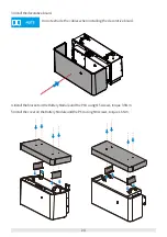
L1
L3
L4=L3+1~2mm
L2=L1+1~2mm
Connect to the
PCU
Connect to the
Battery Module
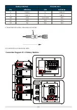
Connect Battery Module power cables in series, which means connect the negative
pole of the Battery Module to the positive pole of the next module.
Connect power cables between the PCU and the Battery Module in parallel, which
means connect postive pole of the PCU power cable to positive pole of the Battery
Module, and negative pole to negative pole.
Do not short-circuit positive and negative pole of the Battery Module when
installing because there is no switch in a single Battery Module.
Power off the Battery System before connecting the power cable to avoid high
voltage danger.
The drawing force of the power cable is at least 1200N after crimping.
Put the seal ring of the waterproof joint in the plastic ring.
Do not disassemble the seal cap if the waterproof joint is not connected to the
cable.
The cross-sectional area of the power cable conductor: 25mm
2
.The cable should
meet standards for outdoor use.
5.4.3 Power Cable Connection
1.Make the power cable used to connect the
PCU
and the Battery Module. Crimp the PIN terminal at one
end of the cable and power OT terminal at the other end.
Grounding Connection Diagram


