19
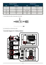
4.Insert the terminal resistance to the COM port of the last Battery Module.
Connection Diagram of 5-8 Battery Modules
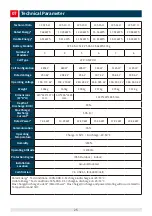
• If there are 5-8 Battery Modules in the Battery System, the power cable between
two rows of Battery Modules should be decided according to the actual
situation.
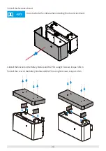
5.Install the decorative board of the Battery Module and the
PCU
.


