


11
and free area is not known, it may be assumed that wood louvers will
have 20-25 percent free area and metal louvers and grilles will have 60-
75 percent free area. Louvers and grilles shall be fixed in the open
position or interlocked with the equipment so that they are opened au-
tomatically during equipment operation.
5.3.6 Special Conditions Created by Mechanical Exhausting or Fire-
places:
Operation of exhaust fans, ventilation systems, clothes dryers, or fireplaces
may create conditions requiring special attention to avoid unsatisfac-
tory operation of installed gas utilization equipment. Air from Inside
Building. See 5.3.3-a.
VI. INSTALLATION POSITIONS
This furnace may be installed in an upright position or horizontal on
either the left or right side panel. Do not install this furnace on its
back. For
upright upflow
furnaces, return air ductwork may be at-
tached to the side panel(s) and/or basepan. For
horizontal upflow
furnaces, return air ductwork must be attached to the basepan. For
both
upright or horizontal counterflow
furnaces, return ductwork must
be attached to the basepan (top end of the blower compartment).
NOTE:
Ductwork must never be attached to the back of the fur-
nace. Contact your distributor for proper airflow requirements and
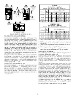
number of required ductwork connections. Refer to “Recommended
Installation Positions” figure for appropriate installation positions,
ductwork connections, and resulting airflow arrangements.
VII. HORIZONTAL APPLICATIONS & CONSIDERATIONS
G
ENERAL
Horizontal applications, in particular, may dictate many of the
installation’s specifics such as airflow direction, ductwork connec-
tions, flue and combustion air pipe connections, etc. The basic ap-
plication of this furnace as a horizontal furnace differs only slightly
from an upright installation. When installing a furnace horizontally,
additional consideration must be given to the following:
ALTERNATE VENT/FLUE
AND COMBUSTION AIR
INTAKE LOCATIONS
FURNACE MUST BE LEVEL
FROM END TO END
FURNACE MUST BE LEVEL
OR SLIGHTLY TILTED FORWARD
WITH THE DOORS 0" - 3/4"
BELOW THE BACK PANEL
DRAIN LINE WITH 1/4" PER FOOT
DOWNWARD SLOPE
36" MINIMUM SERVICE
CLEARANCE REQUIRED
FURNACE MUST BE SUPPORTED
AT BOTH ENDS AND MIDDLE
DRAIN PAN
GAS LINE WITH
DRIP LEG (3" MINIMUM)
4 3/4" MINIMUM
DRAIN TRAP
CLEARANCE
Horizontal Furnace
D
RAIN
T
RAP
AND
L
INES
In horizontal applications the condensate drain trap is secured to
the furnace side panel, suspending it below the furnace. A mini-
mum clearance of 4 3/4 inches below the furnace must be provided
for the drain trap. Additionally, the appropriate downward piping
slope must be maintained from the drain trap to the drain location.
Refer to
Section X, Condensate Drain Trap and Lines
for further
details. If the drain trap and drain line will be exposed to tempera-
tures near or below freezing, adequate measures must be taken to
prevent condensate from freezing.
L
EVELING
Leveling ensures proper condensate drainage from the heat ex-
changer and induced draft blower. For proper flue pipe drainage,
the furnace must be level lengthwise from end to end. The furnace
should also be level from back to front or have a slight tilt with the
access doors downhill (approximately 3/4 inches) from the back
panel. The slight tilt allows the heat exchanger condensate, gener-
ated in the recuperator coil, to flow forward to the recuperator coil
front cover.
A
LTERNATE
V
ENT
/F
LUE
AND
C
OMBUSTION
A
IR
C
ONNECTIONS
In horizontal installations provisions for alternate flue and combus-
tion air piping are available for upflow furnaces with left discharge
and counterflow furnaces with right air discharge. This configura-
tion allows the flue and combustion air piping to be run vertically
through the side of the furnace. Refer to the “Recommended Instal-
lation Positions” figure for further detail. The standard piping con-
nections may also be used in these positions. Refer to
Section IX,
Vent/Flue Pipe and Combustion Air Pipe
for details concerning the
conversion to the alternate vent/flue and combustion air connec-
tions.
AIR
DISCHARGE
AIR
DISCHARGE
AIR
DISCHARGE
Bottom
Return
Duct
Connection
Bottom
Return
Duct
Connection
Bottom
Return
Duct
Connection
Side
Return
Duct
Connection
Side
Return
Duct
Connection
UPFLOW
UPRIGHT
UPFLOW HORIZONTAL
RIGHT AIR DISCHARGE
UPFLOW HORIZONTAL
LEFT AIR DISCHARGE
ALTERNATE FLUE AND
COMBUSTION AIR PIPE
LOCATIONS
ALTERNATE FLUE AND
COMBUSTION AIR PIPE
LOCATIONS
Recommended Installation Positions
NOTE:
Alternate “vertical” piping connections can not be used when
an upflow furnace is installed with supply air discharging to the right,
or when a counterflow furnace is installed with supply air discharging
to the left. In either case, use the standard flue and combustion air
piping connections.
A
LTERNATE
E
LECTRICAL
AND
G
AS
L
INE
C
ONNECTIONS
This furnace has provisions allowing for electrical and gas line con-
nections through either side panel. In horizontal applications the
connections can be made either through the “top” or “bottom” of the
furnace.
D
RAIN
P
AN
A drain pan must be provided if the furnace is installed above a
conditioned area. The drain pan must cover the entire area under
the furnace (and air conditioning coil if applicable).
F
REEZE
P
ROTECTION
Refer to
Section VII, Horizontal Applications and Conditions - Drain
Trap and Lines.
Summary of Contents for GCV9 Series
Page 36: ...36...