background image

57

INSTALLATION DIAGRAM

58

INSTALLATION DIAGRAM

Apartment 2

Apartment 1

 Master Monitor
   372S colour

FA-372

1st Slave Monitor
    372S colour

Master Monitor
  372S colour

1st Slave Monitor
    372S colour

Apartment 1

  Master Monitor
    372S colour

PVS-222 colour
   Door panel 1

12Vdc

FA-372

+

_

SEC

PRI

~

~

230Vac

12Vdc

PVS-222 colour
  Door panel 2 

1st Slave Monitor
    372S colour

2nd Slave Monitor
     372S colour

3rd Slave Monitor
    372S colour

End of line

Off

On

End of line

Off

On

End of line

Off

On

End of line

Off

On

BUS

CV CV

C

NO

BUS

BUS

CV CV

C

NO

BUS

PVS-222 colour
  Door panel 1 

12Vdc

12Vdc

PVS-222 colour
  Door panel 2 

BUS

CV CV

C

NO

BUS

BUS

CV CV

C

NO

BUS

(1)

(1)

25m.

(5) Cable (twisted/ multipaired)

(1)BUS,BUS

Terminal

AWG24: 2 wire (0,20mm²)

--------

(1) BUS, BUS :Maximum distance between furthest door panel and power supply.

50m.

AWG19: 2 wire (0,65mm²)

--------

100m.

AWG19: 2x2 wire (0,65x2=


1,30mm²)

--------

(3) BUS, BUS :Maximum distance between furthest door panel and the last monitor.
                     Maximum distance between Master monitor and Slave monitor: 20m.
                     Place the power supply anywhere on the BUS.

IMPORTANT:

(4) CV, CV :Maximum distance: 5m (cable AWG19).

+

_

SEC

PRI

~

~

230Vac

End of line

Off

On

End of line

Off

On

End of line

Off

On

End of line

Off

On

(2)BUS,BUS

(2) BUS, BUS :Maximum distance between furthest monitor and power supply.
                     Maximum distance between Master monitor and Slave monitor: 20m.

25m.

50m.

50m.

50m.

--------

40m.

CAT6 AWG23: 2 wire (0,26mm²)

--------

80m.

CAT6 AWG23: 2x2 wire
 (0,26x2= 0,52mm²)

--------

100m.

25m.

50m.

50m.

--------

--------

2 wire (1,50mm²)

--------

120m.

80m.

(4)

(4)

(4)

CV, CV

(4)

(4)

(4)

(4)

20m.

(3)BUS,BUS

(5) Only use parallel or twisted cable, not use single-wire cable.

     Do not vary in cross section throughout the entire installation.

onnection to 1 apartment (power supply connected into the bus), 

C

Bus with polarity.

onnection to 2 apartments 

C

(power supply connected into the bus), Bus with polarity.

IMPORTANT:

 To configure the door panel and monitor (see page 45

)

.

                      Only use compatible

 Colour monitor (cód. 

).

 and 54

 372S

11658372

*

IMPORTANT:

 To configure the door panel and monitor (see page 45

)

.

                      Only use compatible

 Colour monitor (cód. 

).

 and 54

 372S

11658372

*

Call to apartment 2.

Call to apartment 1.

Call push button:

(1)

ections chart.

S

BUS

IN

+

_

BUS

OUT

1

2

1

2

Vcc

BUS

IN

+

_

BUS

OUT

1

2

1

2

Vcc

BUS

IN

+

_

BUS

OUT

1

2

1

2

Vcc

BUS

IN

+

_

BUS

OUT

1

2

1

2

Vcc

BUS

IN

+

_

BUS

OUT

1

2

1

2

Vcc

BUS

IN

+

_

BUS

OUT

1

2

1

2

Vcc

BUS

IN

+

_

BUS

OUT

1

2

1

2

Vcc

BUS

IN

+

_

BUS

OUT

1

2

1

2

Vcc

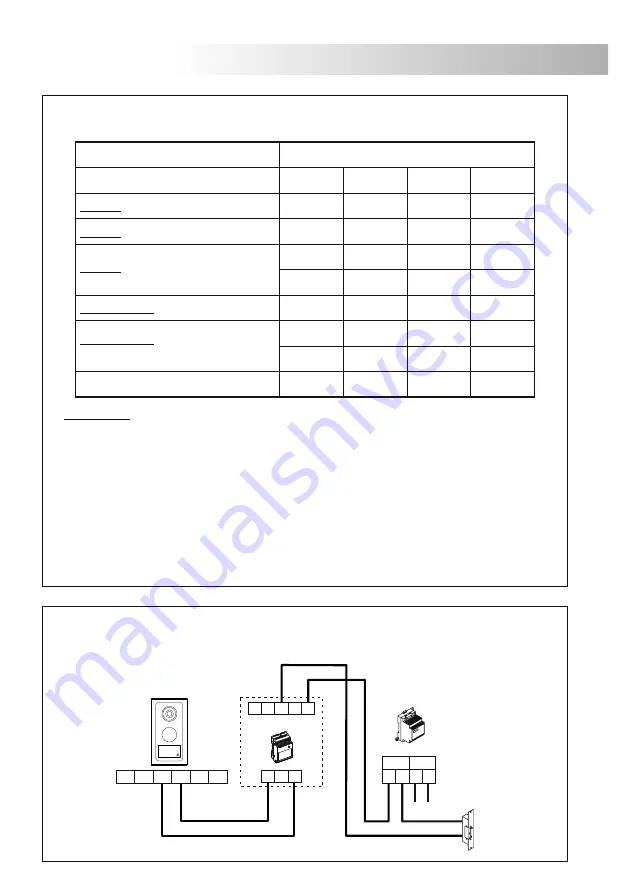
onnection of an a.c. lock release by using TF-104 transformer and 

C

SAR-12/24 relay.

12Vac

SAR-12/24

IN

IN

NC

NA

C

PRI

~

~

~

~

SEC

TF-104

230Vac

 PVS-222
  colour

BUS

CV CV

C

NO

BUS

Summary of Contents for SV-372S Colour

Page 1: ...Instructions manual Video door entry system Kits 2 wires installation SV 372S Color T ML 372 ...

Page 2: ... connection Only use compatible 372S colour monitor cod 11658372 Only use parallel or twisted cable to sections see pages 56 and 58 Do not use single wire cable Do not vary in cross section cable throughout the entire installation O The entire installation must be at least 40 cm away from any other installation otherwise there is a risk that the audio and video signal be exposed to interference or...

Page 3: ...ercom Configuration of the monitor through screen menus using monitor front push buttons Brightness contrast and colour control 4 adjustments for call volume maximum medium minimum and off 4 adjustments for voice volume from minimum to maximum 4 different ring tones selection for door panel call To configure the monitor as Master or Slave To configure the location of the monitor Apartment 1 or apa...

Page 4: ...partments see pages 45 55 and 57 Label push button Wall attachment hook x2 Wiring input hole Monitor audio adjustment Door panel audio adjustment Colour telecamara Installation terminals Microphone Speaker Rainproof cover Configuration dip switches see page 45 a c b m e d d j i g f k Solo abrepuertas de corriente contínua only d c lock release l C CV BUS CV NO h BUS ...

Page 5: ...f the supplied rainproof cover or the installation under a covered place To obtain a good quality picture on video door entry systems avoid direct incidence from light sources sun streetlights It s recommended the use of an external illumination source in case of low light conditions emove the aluminium front R Unscrew the door panel bottom screws With help of an screwdriver remove the aluminium f...

Page 6: ...uit it is accessed by opening the door panel Call push button 1 apartment Call to apartment 1 Call to apartment 1 Call push button 2 apartments Call to apartment 2 Call to apartment 1 1 or 2 apartments mode placed the dip switch 4 to ON to configure the door panel with a system of call to 1 apartment set to OFF for a system of call to 2 apartments End of line mode placed the dip switch 3 to ON in ...

Page 7: ...remove the push button front cover see picture A B The label is now accesible to mark a text see picture C Replace the push button front cover making a light pressure until listenning a click in both sides of the front cover see picture D lose the door panel C DOOR PANEL INSTALLATION Finish the door panel assembly by replacing the aluminium front fix the aluminium front with especified screws With...

Page 8: ... To install the power supply directly on the wall drill two holes of Ø6mm and insert the wallplugs Fix the transformer with the specified screws The power supply can be installed on a DIN 46277 guide simply pressing it To disassemble the power supply from the DIN guide use a plain screwdriver to lever the flange as shown on the picture The FA 372 power supply uses 3 units over DIN guide The power ...

Page 9: ...ed Microphone Speaker Switch End of Line Attachment holes for bracket installation Installation terminals Positive Negative BUS IN Input communication Bus see installation diagrams page 55 and 57 BUS OUT Output communication Bus see installation diagrams page 55 and 57 FA 372 power supply FA 372 power supply _ f e h b a d g BUS OUT 1 c 2 BUS IN 1 2 Vcc ...

Page 10: ... than one door panel pushing each time the picture and audio will switch from a door panel to the other one to establish audio and video communication with the door panel In configuration menu mode To scroll down through the menu or to decrease the value of the selected option see page 53 Push button to activate the lock release During call reception communication and autoswitch on processes it al...

Page 11: ...ting sources in dusty locations or smoky environments The bracket can be fixed using an electrical emmbeding box or directly on the wall To install directly over the wall drill two holes of 6mm and use the supplied screws The upper part of the bracket must be placed at 1 60m height roughly The minimum distance between the monitor and the closest object must be 5cm BUS OUT 1 2 BUS IN 1 2 Vcc BUS OU...

Page 12: ...holes of the monitor with the attachment hooks of the bracket installation With help of an screwdriver fix the monitor with especified screws as shown on the picture onitor wiring M Connect the installation wires to the terminal connector according to the installation diagrams ...

Page 13: ...ommunication press push button on the calling monitor a melody will be reproduced confirming the call is in progress the called monitor s will receive the call To establish communication press push button of the called monitor at any of the monitors If during an intercom communication a call is made from the door panel the intercom function will be cancelled a melody will be reproduced confirming ...

Page 14: ... exit the menu press push button twice To modify the contrast of the monitor choose the Video option with help of the scroll buttons and select this option by pressing the button the following menu will be displayed Then choose the Contrast option and select it increase or decrease according to the desired value To exit the menu press push button twice To modify the color of the monitor choose the...

Page 15: ...tion menu mode To scroll up through the menu to increase the value of the selected option To scroll down through the menu to decrease the value of the selected option Select deselect the desired option MONITOR ADJUSTMENTS PROGRAMMING To link the monitor to one apartment choose the ID option with help of the scroll buttons and select this option by pressing the button the following menu will be dis...

Page 16: ...tor 372S colour Apartment 1 Master Monitor 372S colour PVS 222 colour Door panel 1 FA 372 _ SEC PRI 230Vac PVS 222 colour Door panel 2 1st Slave Monitor 372S colour 2nd Slave Monitor 372S colour 3rd Slave Monitor 372S colour End of Line Off On End of Line Off On End of Line Off On End of Line Off On Call push button 1 PVS 222 colour Door panel 1 _ SEC PRI 230Vac PVS 222 colour Door panel 2 End of ...

Page 17: ...aximum distance 5m cable AWG19 3 CV CV Maximum distance 5m cable AWG19 IMPORTANT 4 Only use parallel or twisted cable not use single wire cable Do not vary in cross section throughout the entire installation 25m 1 BUS BUS AWG24 2 wire 0 20mm 2 3 CV CV _ 50m AWG19 2 wire 0 65mm 2 3 100m AWG19 2x2 wire 0 65x2 1 30mm 2 3 50m CAT6 AWG23 2 wire 0 26mm 2 3 100m CAT6 AWG23 2x2 wire 0 26x2 0 52mm 2 3 100m...

Page 18: ...C NO BUS 1 1 _ SEC PRI 230Vac End of line Off On End of line Off On End of line Off On End of line Off On onnection to 1 apartment power supply connected into the bus C Bus with polarity onnection to 2 apartments C power supply connected into the bus Bus with polarity IMPORTANT To configure the door panel and monitor see page 45 Only use compatible Colour monitor cód and 54 372S 11658372 IMPORTANT...

Page 19: ... distance 5m cable AWG19 2 BUS BUS 2 BUS BUS Maximum distance between furthest monitor and power supply Maximum distance between Master monitor and Slave monitor 20m 25m 50m 50m 50m 40m CAT6 AWG23 2 wire 0 26mm 80m CAT6 AWG23 2x2 wire 0 26x2 0 52mm 100m 25m 50m 50m 2 wire 1 50mm 120m 80m 4 4 4 CV CV 4 4 4 4 20m 3 BUS BUS 5 Only use parallel or twisted cable not use single wire cable Do not vary in...

Page 20: ...don t receive calls w Check the output power supply voltage between and is of 17Vd c Otherwise disconnect the power supply from the installation and measure again If its correct now it means there is a short circuit in the installation Disconnect the power supply from the mains and check the installation w Check the power supply polarity wiring installation with power supply connected to monitor s...

Page 21: ...60 NOTAS NOTES ...

Page 22: ...61 NOTAS NOTES ...

Page 23: ...62 NOTAS NOTES ...

Page 24: ... 218 5542 Mobil 30 940 1970 30 959 0930 GOLMAR HU E mail info delton hu Web www delton hu 1141 Budapest Fogarasi út 77 Tel 220 7940 220 7814 220 7959 220 8881 364 3428 Fax 220 7940 Mobil 30 531 5454 30 939 9989 A dokumentáció a Delton szellemi tulajdona ezért annak változtatása jogi következményeket vonhat maga után A fordításból illetve a nyomdai kivitelezésből származó hibákért felelősséget nem ...

Reviews: