background image


18 


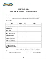
REFERENCE NOTES 

Tornado Boat Lift (2-Cylinder) 

 Capacity: 8K / 10K / 12K 


INSTALLATION PROVIDER: ___________________________________________________       INSTALLATION DATE: _________________________ 


INSTALLATION ADDRESS: _______________________________________________________________________________________________________ 


INSTALLATION CHECKLIST: 
 

STEP 

DATE/TIME 

INITIAL 

NOTES 


SAFETY REQUIREMENTS 


PART/HARDWARE IDENTIFICATION TABLE 


MOUNT CROSS BEAM 


ATTACH FOOT PAD 


MOUNT SIDE BEAM 


ATTACH LOWER CYLINDER MOUNT 


MOUNT STERN SIDE H-FRAME 


MOUNT BOW SIDE H-FRAME 


MOUNT HYDRAULIC CYLINDER(S) 


MOUNT ALUMINUM MULTI-BUNK 


ATTACH GUIDE POLE MOUNTING BRACKET 


ATTACH GUIDE POLE 


COMPLETE WALKTHROUGH OF THE 

HYDRAULIC POWER PACK OPERATING 

MANUAL


I, _____________________________________, hereby verify that all guidelines and procedures were read and followed to the best of my 
ability. 

SIGNATURE : ____________________________________________


DATE OF COMPLETION: _____________________________


Summary of Contents for Tornado 4-CYLINDER

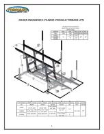
Page 1: ...17611 East St North Fort Myers FL 33917 239 337 4141 GoldenMarineSystems com GoldenBoatLifts com REVISION A PUBLISHED 7 15 2020 INSTALLATION MANUAL MODEL 4 CYLINDER ...

Page 2: ... Stainless Steel Shafts Hydraulic Cylinder Shafts are Protected with the Exclusive Air Bellows Larger Structural Components Prevent Flex and Wear our Lifts are much Heavier than all Others The Golden Exclusive Multi Bunk Can Accommodate V hulls Step Hulls Pontoon and Deck Boats As Well As PWCs Optional and Removable Accessories Such as Adjustable Guide Poles with Cushions Bumpers or Optional Walkw...

Page 3: ... the Tornado Boat Lift Failure to reference and follow these instructions before attempting to operate the Tornado Boat Lift may cause damage to the lift and or personal injury death After completing the steps outline in the TORNADO INSTALLATION MANUAL and the HYDRAULIC POWER PACK INSTALLATION MANUAL the Tornado Boat Lift should be ready to operate Note Before operation it is important to verify t...

Page 4: ...4 ...

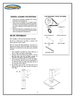
Page 5: ...m Guide Pole Mount REQUIRED TOOLS Wrench 9 16 Wrench 3 4 Pliers Mallet Pry Bar HARDWARE IDENTIFICATION Hinge Bearing Cotter Pin Lock Washer Hinge Pin Hex Nut Hex Bolt Cylinder Pin Lollipop Washer Flat Washer 1 2 20 3 8 52 8 1 8 16 3 4 8 8 1 2 20 3 8 52 1 2 X 3 1 2 20 3 8 X 5 8 3 8 X 4 1 2 36 3 8 X 1 1 2 8 3 16 16 1 2 40 3 8 88 3 4 8 Note Hardware amounts may vary depending on optional accessories ...

Page 6: ...to desired height 2 Attach one 1 3 8 Flat Washer onto two 2 3 8 x 4 1 2 Hex Bolts and insert them into Leg Pocket securing the Crossbeam to the Square Tube Leg shown in Figure 2 3 Attach one 1 3 8 Flat Washer one 1 3 8 Lock Washer and one 1 3 8 Hex Nut over the two 2 protruding ends of the Hex Bolts and securely fasten with appropriate wrench until secure as shown in Figure 2 4 Repeat these steps ...

Page 7: ...igure 3 2 Attach one 1 3 8 Flat Washer to one 1 3 8 Hex Bolt and insert through hole s in the Foot Pad and Square Tube Leg as shown in Figure 3 3 Attach one 1 3 8 Lock Washer and one 1 3 8 Hex Nut to the protruding end of the Hex Bolt and securely fasten with appropriate wrench until secure 4 Repeat these steps for the remaining three 3 Foot Pads PARTS REQUIRED TO ATTATCH FOOT PAD Foot Pad 4 3 8 F...

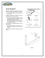
Page 8: ...les on the bottom of the Side Beam Saddle as shown in Figure 5 3 Attach one 1 3 8 Flat Washer one 1 3 8 Lock Washer and one 1 3 8 Hex Nut to the two 2 protruding ends of the Hex Bolts and hand tighten Note It is important not to over tighten Hex Nuts to allow for Side Beam adjustability 4 Repeat these steps three 3 more times once for the opposite side of the Side Beam and twice for the second Sid...

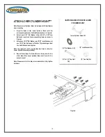
Page 9: ...er one 1 1 2 Lock Washer and one 1 1 2 Hex Nut to each of the five 5 protruding ends of the Hex Bolts and hand tighten Note It is important not to over tighten Hex Nuts to allow for Lower Cylinder Mount adjustability 4 Repeat these steps for three 3 more times once for the other side of the Lower Cylinder Mount and twice for the second mount Note Please return to this step when instructed to fully...

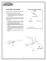
Page 10: ...into one 1 3 4 x 5 Hinge Pin bending the tines of the Cotter Pin outward and apart securing the Cotter Pin within the Hinge Pin 3 Attach a Lollipop Washer to the open end of the Hinge Pin 4 Slide the Hinge Pin through the hinge plate as shown in Figure 8 5 Insert one 1 Lollipop Washer and one 1 1 8 Cotter Pin into the protruding end of the Hinge Pin bending the tines of the Cotter Pin outward and ...

Page 11: ...and apart securing the Cotter Pin within the Hinge Pin 3 Attach a Lollipop Washer to the open end of the Hinge Pin 4 Slide the Hinge Pin through the hinge plate as shown in Figure 10 5 Insert one 1 Lollipop Washer and one 1 1 8 Cotter Pin into the protruding end of the Hinge Pin bending the tines of the Cotter Pin outward and apart securing the Cotter Pin within the Hinge Pin 6 Repeat this step fo...

Page 12: ... lower mounting hole as shown in Figure 11 3 From the inside of the hinge plate insert one 1 3 8 Hex Bolt through the hinge plate and the lower hole on the Cylinder Pin 4 Attach one 1 3 8 Lock Washer and one 1 3 8 Hex Nut to the protruding end of the Hex Bolt and fasten with appropriate wrench until secure as shown in Figure 11 5 Repeat these steps for the remaining three 3 Hydraulic Cylinders PAR...

Page 13: ... through the Hydraulic Cylinder upper mounting hole as shown in Figure 13 3 From the inside of the mounting plate insert one 1 3 8 Hex Bolt through the mounting plate and the hole on the Cylinder Pin shown in Figure 13 4 Attach one 1 3 8 Lock Washer and one 1 3 8 Hex Nut to the protruding end of the Hex Bolt and fasten with appropriate wrench until secure as shown in Figure 13 5 Repeat these steps...

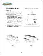
Page 14: ...e 14 3 Attach a 3 4 Flat Washer over the Hinge Pin and insert it into the bunk support as shown in Figure 15 Note Do not fully insert Hinge Pin through H Frame until completing next step 4 Insert a Lollipop Washer between the Bunk and the H Frame on both sides as shown in Figure 15 before fully inserting the Hinge Pin through the H Frame and out of the opposite side of the Bunk 5 Attach a 3 4 Flat...

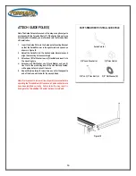
Page 15: ...ent tube is angled upward toward the outside of the lift and downward toward the inside of the lift as shown in Figure 17 3 Attach one 1 3 8 Flat Washer over two 2 Hex Bolts and insert into the corresponding holes in the Bunk support as depicted in Figure 16 4 Attach one 1 Lock Washer and one 1 Hex Nut to each of the protruding Hex bolts and fasten with appropriate wrench until secure 5 Repeat thi...

Page 16: ...r to one 1 Hex Bolt and insert into the mounting hole 4 Attach one 1 Flat Washer one 1 Lock Washer and one 1 Hex Nut to the protruding end of the Hex Bolt and fasten with appropriate wrench until secure 5 Repeat this step three 3 more times once for the opposite end of the Bunk and twice for the second Bunk Note It is important to review all the steps in this manual before operating the Tornado Bo...

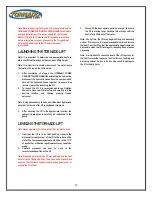
Page 17: ... 3 After securing the lift in the appropriate location the hydraulic hoses should carefully be reattached to the pump LEVELING THE TORNADO LIFT Note Never operate a lift while on the lift or inside the boat 1 Now that the lift is in its final position measure the distance from each corner of the lift to the surface of the water The four measurements should all be within 1 1 2 of each other otherwi...

Page 18: ...MENTS PART HARDWARE IDENTIFICATION TABLE MOUNT CROSS BEAM ATTACH FOOT PAD MOUNT SIDE BEAM ATTACH LOWER CYLINDER MOUNT MOUNT STERN SIDE H FRAME MOUNT BOW SIDE H FRAME MOUNT HYDRAULIC CYLINDER S MOUNT ALUMINUM MULTI BUNK ATTACH GUIDE POLE MOUNTING BRACKET ATTACH GUIDE POLE COMPLETE WALKTHROUGH OF THE HYDRAULIC POWER PACK OPERATING MANUAL I _____________________________________ hereby verify that all...

Reviews: