


14
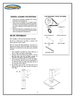
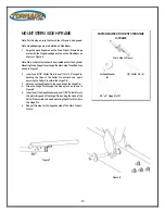
Figure 14
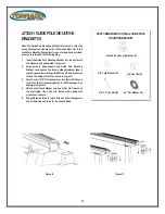
Figure 15
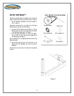
Note: Before proceeding to the following steps, please revisit
steps with asterisks (3 & 4) and use a wrench to tighten all
hardware that was originally hand tightened. Failure to tighten
all hardware as described can cause damage to the Tornado Boat
Lift and/or serious injury/death.
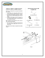
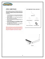
MOUNT ALUMINUM MULTI-BUNK
1.
Align the 3/4” hole in the Aluminum Multi
-Bunk with the
corresponding mounting hole in the top of the Stern Side H-
Frame.
2.
Insert one (1) 1/8” Cotter Pin into one end of a 3/4" Hinge Pin.
Using Pliers, bend the tines apart and away from each other,
securing it to the hinge pin as shown in Figure 14.
3.
Attach a 3/4" Flat Washer over the Hinge Pin and insert it
into the bunk support as shown in Figure 15.
Note: Do not fully insert Hinge Pin through H-Frame until
completing next step.
4.
Insert a Lollipop Washer between the Bunk and the H-
Frame on both sides as shown in Figure 15 before fully
inserting the Hinge Pin through the H-Frame and out of the
opposite side of the Bunk.
5.
Attach a 3/4" Flat Washer and 1/8” Cotter Pin to the
protruding end of the Hinge Pin. Using Pliers, bend the tines
apart and away from each other, securing it to the hinge pin
as shown in Figure 14.
6.
Repeat this step three (3) more times, once for the opposite
end of the Bunk, and twice for the second Bunk.
PARTS REQUIRED TO MOUNT ALUMINUM
MULTI-BUNK
Aluminum Multi-Bunk (2)
3/4" Hinge pin (4)
Lollipop Washer (8)
3/4" Flat Washer (8)
1/8” Cotter Pin (8)
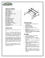
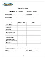
Summary of Contents for Tornado 4-CYLINDER
Page 4: ...4 ...


