45
Supplying Power to the
Remote Unit and the
Pro-Reel
®
Control Box
Refer to figure 2 on page 1 for information on
the locations of the various parts.
CAUTION:
Ensure that battery polarity is
correct when inserting batteries into the
remote unit battery
compartment.
WARNING:
Do NOT use the nominally 1.5V
Lithium cells in the remote unit as these are in
fact above
1.8V when new and may result in damage to
the remote unit. Use only high quality 1.5V
alkaline cells for
good performance and product reliability.
For the remote unit, ensure that a suitable pair
of 1.5V cells are inserted correctly into the unit.
The battery cover
is on the rear of the unit at the base. Two size
‘AAA’ cells will be required. Spring contacts in
the battery holder
always connect to the negative ends of the
cells. Also under the battery cover can be
found the configuration
socket (see figure 2 on page 1) which is a
2.5mm socket. This is used to connect the
remote unit and the control
box together with the supplied configuration
cable to enable programming of remote unit
buttons to control box
relays. The battery holder must be removed in
order to access the configuration socket of the
remote unit, but the
batteries should be left in the holder to ensure
that the remote unit is still powered.
The Pro-Reel® control box should already
be suitably configured with 12V DC vehicle
battery power.
Pro-Reel
®
Control Box
Configuration
Configuration of the system is required if
replacing a damaged or lost remote (hand held
transmitter) unit, since
each transmitter and receiver are paired using
unique identifier codes.
2.1
Configuring a Remote Unit to control a
Control Box’s relays.
In the event that a remote unit must
be replaced or a new one added to an
existing configuration, the following steps
will enable a new remote unit to be used
with an existing control box. The location
of relevant parts can be identified using
figure 2 on page 1.
CAUTION:
Do not touch any component in the
control box except those parts referred to
in the following procedure.
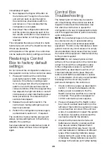
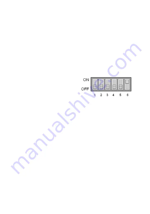
1. Check that the DIP switch (SW1 in the
control box) is set as follows:
Figure 3: DIP Switch (SW1) setting. Note that
all switches are in the OFF position except
switch 6.
2. Connect the configuration cable between
the remote unit and the control box via the
configuration sockets. If done successfully,
the red light of each unit will light up
continuously. If both lights do not ensuring
that neither light is lit and then reconnect
the cable. (If, after several attempts to
establish the configuration connection, the
lights do not both remain lit, then consult
the troubleshooting section, section 3, of
this manual.)
3. Once the red lights of both the remote unit
and the control box remain lit while the
configuration cable is connected, press
and hold push-button switch, SW2, in the
control box until the control box’s red light
turns off, then release the push-button
switch. The control box’s red light should
remain off but the remote unit’s red light
should still be on.
4. On the remote unit, depress the Rewind
button. The light on the remote unit should
turn off and the light in the control box
should very briefly turn on and then

