8
RELAY CONTROL SYSTEM ELECTRICAL INSTRUCTIONS
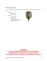
Enable power to the operator and observe the LEDs on the photo-eye head unit. The RED and YELLOW
LEDs should be illuminated. When the crossbeam is broken (blocked) the RED LED should go out and
the GREEN LED should illuminate. Adjust the mechanical alignment of the head unit and the sensitivity
of the circuit to ensure reliable and robust operation. Close the clear plastic door and re-install the
protective rubber cap.
SETUP AND OPERATION:
After the power wiring has been installed (and power has been enabled to the unit) it will be
necessary to set the curtain door end-stop positions. Care should be exercised during these
operations to avoid damage to the assembly and ensure a long service life of the unit. The door
will open with only a momentary pressing of the “Open” button, but it will be necessary to press
and hold the “Close” button in order to get the door to move down. This functionality will be
changed when you do the final programming.
LIMIT & INTERNAL SAFETY SWITCH:
-
Locate the 6 conductor wire marked ‘control’ and remove the insulative material, preparing
each conductor to make the following connections; (SEE NEXT PAGE FOR DIAGRAM)
o
Blue from 6 conductor to N/C side (right) of open limit switch
o
Black from 6 conductor to N/C side (right) of close limit switch
o
White from 6 conductor to COM side (left) of open limit switch
o
Green from 6 conductor to COM side (left) of close limit switch
o
Orange from 6 conductor to yellow thermal protection wire
o
Red from 6 conductor to black from hand crank safety switch
o
Gray from hand crank safety switch to its own connector
Middle column on limits
not used


