


2
RELAY CONTROL SYSTEM ELECTRICAL INSTRUCTIONS
115VAC POWER WIRING:
The external operator requires 115VAC, 60Hz with a current draw of 5A (1/2 HP PSC
inductive motor). Make sure that the branch circuit and conductor size can support
this load requirement. Low voltage can cause erratic behavior and operator
overheating.
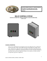
Locate the rotary selector switch on the printed circuit board and ensure that it is set to
“C2” (position 0) as shown in the following photo:
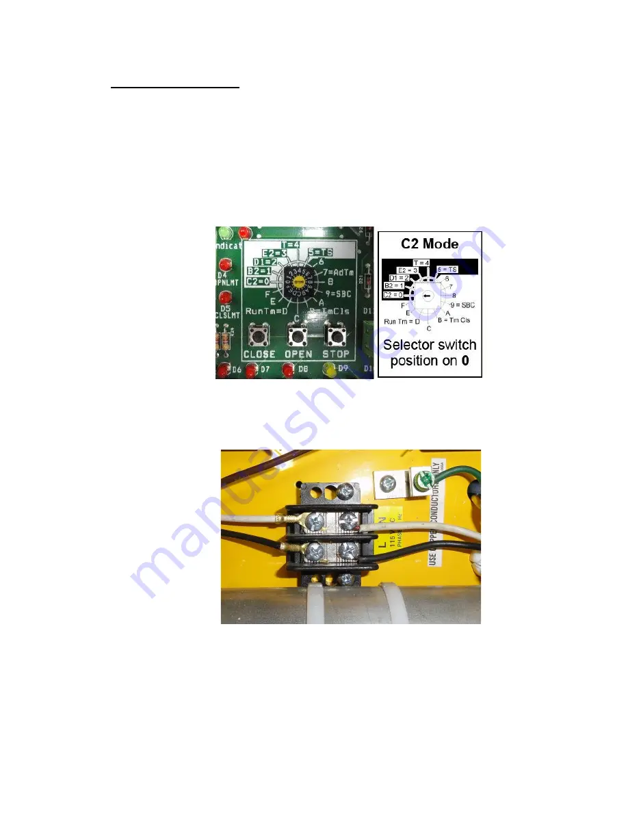
Power and ground are connected to the operator as shown in the following photo
(Photo 19):


