14
RELAY CONTROL SYSTEM ELECTRICAL INSTRUCTIONS
Locking NEMA-4:
Although the color codes are arbitrary, Goff’s has selected the following standard:
Green
-
Common
Red -
Stop
Yellow
-
Stop Return
Blue
-
Open (UP)
White
-
Close (DOWN)
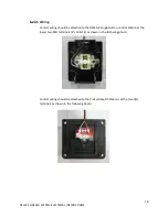
Remove the cover of the Locking NEMA-4 station and note the location of the N/O and
N/C terminals for each button. The N/O terminals are located closer to the base and are
on the “right” side of the station. The N/C terminals are raised and are on the “left”
side.
Use a short piece of green wire from the 5-
conductor “Thermo Wire” and jumper
between one of the N/O terminals on the Open button and one of the N/O terminals on
the Close button. Make another jumper between the Close button terminal and the top
N/O terminal on the Lock. Connect the free end of the green wire in the 5-conductor
bundle to the bottom N/O terminal on the Lock.
Connect the rest of the wires as shown in the following photo. Note that the yellow and
red wires go to the N/C terminals on the Stop button.
Route the cable through one of the station knockouts and carefully reinstall the cover. Make sure that
the cover is installed properly and that the buttons work freely.


