4
RELAY CONTROL SYSTEM ELECTRICAL INSTRUCTIONS
The operator supports NEMA-1 and NEMA-4 3-
button control stations with N/O “Open” and “Close”
buttons.
The “Stop” buttons must be N/C. The low
-voltage control connections for the primary (first)
station should be made with the 4-
conductor “Thermo Wire” that was included with your kit. Although
the color codes are arbitrary, Goff’s has selected the follow
ing standard:
LIMIT & INTERNAL SAFETY SWITCH:
-
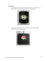
Locate the 6 conductor wire marked ‘control’ and remove the insulative material, preparing
each conductor to make the following connections; (SEE NEXT PAGE FOR DIAGRAM)
o
Blue from 6 conductor to N/C side (right) of open limit switch
o
Black from 6 conductor to N/C side (right) of close limit switch
o
White from 6 conductor to COM side (left) of open limit switch
o
Green from 6 conductor to COM side (left) of close limit switch
o
Orange from 6 conductor to yellow thermal protection wire
o
Red from 6 conductor to black from hand crank safety switch
o
Gray from hand crank safety switch to its own connector
Middle column on limits
not used


