7
RELAY CONTROL SYSTEM ELECTRICAL INSTRUCTIONS
Additional NEMA-1 and NEMA-4 control stations (along with Pull Cord and RF Interfaces) can be added
to the Goff’s operator. Please see the “Addendum” at the end
of these assembly instructions for further
wiring information.
PHOTO-EYE:
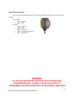
The OEM cable for the photo-eye will not be long enough to reach the external operator in many
installations. We have included a junction box, cover, glands, wire nuts, and some additional 4-
conductor wire so that an extension can easily be fabricated.
The wiring convention for the photo-eye is as follows:
Brown
-
(1) 24Vac (Power)
Blue
-
(2) 24Vac (Power)
Black
-
(5) SENS
Orange
-
(3) COM
White
-
Not Used
Remove the protective rubber cap from the photo-eye head unit and open the clear plastic door. Set
the slide switch to “Dark Operation” (DK) by sliding it to the “left”.


