background image


Important Safety Instruction

1)  Read all of these instructions.
2)  Save these instructions for later use.
3)  Follow all warnings and instructions marked on the product.
4)  Follow all instructions.
5)  Do not use the apparatus near water.
6)  Clean only with dry cloth.
7)  Do not block any ventilation openings. Install in accordance with the manufacturer´s instructions.
8)  Do not install near any heat sources such as radiators. Heat registers, stoves, or other apparatus (including ampli

fi

 ers) 


that produce heat.

9)  Do not defeat the safety purpose of the polarized or grounding-type plug. A polarized plug has two blades with one wider 
 

than the other. A grounding type plug has two blades and a third grounding prong. The wide blade or the third prong are 


provided for your safely. If the provided plug does not 

fi

 t into your outlet. Consult an electrician for replacement of the 

 obsolete 

outlet. 

10)  Product the power cord from being walked on or pinched particuralry at plugs, convenience receptacles, and the point 
 

where they exit from the apparatus.

11)  Only use attachments/accessories speci

fi

 ed by the manufacturer.

12)  Do not place the apparatus on an unstable cart, stand or table. The apparatus may fall, causing serious damage to the 
 apparatus.
13)  Unplug this apparatus during lightning storms or when unused for long periods of time. 
14)  Refer all servicing to quali

fi

 ed service personnel. Servicing is required when the apparatus has been damaged in any way,


such as power-supply cord or plug is damaged, liquid has been moisture, does not operate normally, or has been 

 dropped. 
15)  The apparatus shall not be exposed to dripping or splashing and that no objects 

fi

 lled with liquids, such as vases, shall be 


placed on the apparatus.    

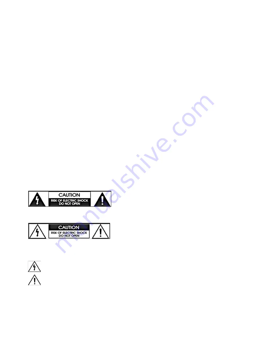
Shock Hazard Marking and Associated Graphical symbols

Explanation of Safety Related Symbols

WARNING:  To Reduce The risk of 

fi

 re or electric shock, do not                     


expose this apparatus to rain or moisture. 

CAUTION:   TO REDUCE  THE RISK OF LELCTRIC SHOCK,             
         

DO NOT REMOVE COVER (OR BACK). NO USER  


-  SERVICEABLE  PARTS  INSIDE.  REFER  SERVICING                      


TO QUALIFIED SERVICE PERSONNEL.

This symbol is intended to alert  the user to the presence of uninsulated “dangerous voltage “ Within the product’s 
enclosure that may be of suf

fi

 cient magnitude to constitute a risk of electric shock to persons. 

This symbol is intended to alert the user to the presence of important operating and maintenanc (servicing) 
instructions in the literature accompanying the appliance.

WARNING: To Reduce The risk of 

fi

 re or electric shock, do not  expose this apparatus to rain or moisture

The main Socket - outlet for connecting mains plug shall be accessibly close to this apparatus.

1

Summary of Contents for GS 8010

Page 1: ...USER S MANUAL GS 8010...

Page 2: ...apparatus 13 Unplug this apparatus during lightning storms or when unused for long periods of time 14 Refer all servicing to qualified service personnel Servicing is required when the apparatus has b...

Page 3: ...na Setup 10 2 1 2 Satellite Scan 11 2 1 3 Advanced TP Scan 11 2 1 4 Edit TP Satellite 12 2 2 DVB T Setup option 13 2 2 1 Automatic Scan 13 2 2 2 Manual Scan 13 2 2 3 Antenna Power 13 2 3 Channel List...

Page 4: ...should fall into the cabinet Use a soft cloth and a mild solution of washing up liquid to clean the case Do not connect or modify cables when the unit is plugged in Do not allow the unit to be expose...

Page 5: ...tronic Program Guide Multi language OSD 10000 Channels TV Radio program Timer Function Automatic Turn On Off by Setting Function RTC Real Time Clock 5 Favorite List Unlimited Programs per each Powerfu...

Page 6: ...only NOTE Front could be changed according to the model option 2 Rear Panel 1 IF INPUT IF INPUT from LNB to receiver 2 IF OUTPUT IF Loop through output to 2nd receiver 3 TV SCART TV Scart output 4 VC...

Page 7: ...13 OK Go to channel list or confirm menu 14 EPG Show Electronic Program Guide but information is only show if program providers transmit program information 15 INFO Give short program information abo...

Page 8: ...r IN and audio L R IN of TV Set STB s video output mode to 1080i or 720p or 576p using V FORMAT key of remote controller Please check TV s user manual for detail connecting method of the YPbPr input p...

Page 9: ...channel name satellite name current time and date 1 4 EPG Electronic Program Guide EPG data is transmitted with transport stream signaled by program provider Press EPG button to see program schedule i...

Page 10: ...When the subtitle data in the channel 1 Press Sub key 2 Select language that you want 3 Select Off in the subtitle menu to exit 2 Main Menu Please follow the brief procedure below and watch the satel...

Page 11: ...ellite a Current position Select the position number by using keys 0 26 default 27 49 user define b Movement Select East West by using keys c Store Please select Store and the current position will be...

Page 12: ...ed through LNB in common When you press OK key TP List will be displayed and if you press Left Right key on RCU you can select Multi TP 3 Polarity Select Horizontal or Vertical by using keys 4 Symbol...

Page 13: ...searched channels cannot be deleted To restore the deleted satellite move the cursor to the deleted satellite and press OK Then select Restore in the screen and press OK key 4 How to add a new transp...

Page 14: ...of network scan by using key 5 Select 7 or 8MHz Bandwidth by using Key 6 Press the OK key to start channel searching 2 2 3 Antenna Power 1 Select the Antenna Power 2 You can switch the power supply O...

Page 15: ...el All channel Satellite DVB T option Press OK key and all selected channels are deleted 4 LOCK Select P LOCK and press OK Select the channel that you want to lock and press keys Release locked channe...

Page 16: ...selecting Time mode you can adjust the time as follows 2 Timer After selecting Timer you can see Timer list and adjust the time as follows 3 Timer Mode Once Daily 4 Wakeup Time Set up by pressing nume...

Page 17: ...able language by using VOL keys 2 Audio Language Select the preferable Audio language by using the keys 3 Subtitle Language Select the preferable Subtitle language by using the keys 2 5 4 A V Setting...

Page 18: ...cannot meet DC5V Max 100mA 1 After inserting USB Stick in Normal Video mode USB menu will be displayed 2 Flash ROM Writing file is in Code Backup folder and CH Data is in Channel Data Backup folder 3...

Page 19: ...e name on the menu screen On choosing this menu you can access different options available with the type of the CAM e g Consultation Authorization Module Information and etc The user can receive the s...

Page 20: ...LNB Check the position of the dish realign dish if necessary If you are using a DiSEqC 1 0 switch check that you have connected the LNBs to the correct connections on the switch Distorted menu screen...

Page 21: ...l output HDMI HDCP YPbPr Video RCA 1 output Audio RCA 2 output Digital Audio 1 optical output S PDIF Front Panel VFD LED Channel Number Display 8 Keys Power Channel Down up Volume up down Menu Exit OK...

Reviews: