Go!Control 2GIG-CP2 Installation & Programming Instructions Download Page 5

3

System Overview

The system’s Control Panel features a color touch screen display that 
allows control of all system functions and programming. The display 
clearly shows the installer and subscriber system and installation 
status. The helpful scrolling text, along with the voice prompts 
that the Control Panel sounds, make installation, programming, 
and operation very easy compared to keypad-programmed and 
operated security systems of the past.

The system supports 48 wireless sensors of various types, two 
hardwire loops, 15 sensor response types, a supervised bell output, 
and a programmable solid-state control output. An on-board digital 
communicator reports alarms and trouble to a central monitoring 
station receiver via the standard telephone network. The Control 
Panel also supports 2-way voice communications with the Central 
Station.

An internal 345 MHz narrow-band radio receiver detects signals 
from wireless system sensors. The high-gain receiver allows for 
easy placement of the wireless sensors so signals can be received 
in even the toughest of installation environments.

When the optional Model 2GIG-XCVR2 900 MHz transceiver is 
installed, it sends and receives signals with accessory wireless 
touch screen keypads. Touch screen keypads allow remote control 
of the system through the same graphic interface design as the 
Control Panel.

For enhanced operation, an optional Model 2GIG-GSMx global 
system for mobile communications module (GSM radio modem) 
can be installed in the fi eld. With the optional GSM radio modem 
installed, the system will have wireless Central Station reporting 
capability. 2-way voice communication with the Central Station can 
also go “over-the-air” through the GSM radio modem.

The optional GSM radio modem also allows 2-way communications 
with the Alarm.com server. Through this server, subscribers can 
query and control their system using a computer browser from 
anywhere in the world. The Alarm.com server can also send 
messages, time corrections, and software updates to the Control 
Panel. Special messages from the server are displayed to the 
subscriber on the Control Panel’s color touch screen.

For home control, the Control Panel’s built-in Z-Wave radio module 
allows controlling and monitoring various home automation devices 
such as lighting, locks, heating, and air conditioning.

Eight user codes including a duress code are supported. User 
“one” is the master code that can add or delete the other seven 
user codes. The Installer Code has access to system programming.

The front panel 


and


buttons serve as controls as well as 

indicators. Pressing the 


button displays emergency icons on the 

display for Panic, Fire, and Emergency alarm activation (each has 
programmable options and can be enabled or disabled). Pressing 
the 


button changes the system display to the Home Screen.

C P U


Piezo

Siren

Smoke

Sensors

PIR

Motion

Sensors

Key

Fobs

Panic

Buttons

Door /

Window

Sensors

Wireless
Keypads

Wireless

Touch

Screens

Up to 48 Wireless Sensors per System

Standard 345 MHz Receiver

or Optional

345 MHz / 900 MHz Transceiver

CO

Sensors

Glass
Break

Sensors

Hardwire

Loop

#1

Speaker

&

Microphone

V

oice

Siren

CONTROL PANEL

Hardwire

Loop

#2

Existing

Sensor

Installation

Hardwire Inputs

Subscriber

Touch Screen

Digital

Comm

unicator

Subscriber’s

Computer

Subscriber’s

PDA

Cell
Site

Alarm.com

Web site

Central Station

Receiver

Public

Switched

Telephone

Network

GSM

Telephone

Network

Thermostat

Z-Wave

Radio

Lighting

Control

Door

Locks

Power

Supply

System

Power

Bell

Output

120 VAC

Input

Power

Alarm.com

Server

Optional

GSM

Module

Color LCD

Display with

Touch Screen

Color Display

Home &

Emergency

Buttons

Alarm.com

Infrastructure

Database

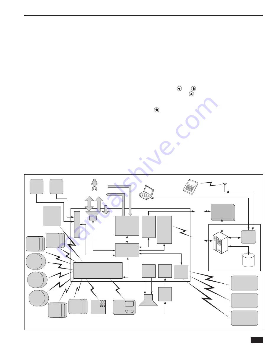
Figure 3.   System Block Diagram

Summary of Contents for 2GIG-CP2

Page 1: ...Wireless Security System Installation Programming Instructions 2GIG CP2...

Page 2: ...e ceiling Do not install smoke alarms where normal ambient temperatures are above 100 F 37 8 C or below 40 F 4 C Also do not locate alarm in front of air conditioners heating registers or other locati...

Page 3: ...14 Sounder Disable Icon 14 Backup Battery Status Icon 14 Test Mode Icon 14 Touch Screen Keypad Traffic Icon 14 GSM Radio Icon 14 Interior Sensor Open Icon 14 Programming Navigation 15 Navigation Arro...

Page 4: ...these requirements to qualify for a discount For an ETL smoke alarm system use only approved model smoke detectors with this Control Panel NOTE Some cities and municipalities may require an alarm syst...

Page 5: ...allows 2 way communications with the Alarm com server Through this server subscribers can query and control their system using a computer browser from anywhere in the world The Alarm com server can a...

Page 6: ...ORANGE when ANY sensor is open not ready to arm Flashes RED while system is armed HOME BUTTON INDICATOR THIRD HAND HANGER STRAP Hooks onto mounting plate during installation to hold the Control Panel...

Page 7: ...ery connector into the connector on the Control Panel s circuit board 14 Swing the Control Panel up placing the bottom over the lip of the mounting bracket Push the top of the Control Panel into the m...

Page 8: ...5 second button lockout Lithium battery 345 MHz ETL Listed 2GIG GB1 Glass Break Detector Monitors for the sound of breaking glass Two test LEDs Dual shatter recognition technology thud then crash Lith...

Page 9: ...module Locking connector 2GIG ANT4X External In wall GSM Antenna Antenna installs in the wall behind Control Panel 2 foot cable Plugs into GSM module Locking connector 2GIG BATT1 Standard Battery Pac...

Page 10: ...nd of line resistors EOLR can also be used to supervise the loops Only contacts should be used with the hardwired loops The Control Panel does not support powering external devices PIR s etc NOTE HARD...

Page 11: ...nd the GREEN cable wire to the box TIP 4 At the demarcation box connect the BLACK cable wire to the house telephone RING wire s and the YELLOW cable wire to the house telephone TIP wire s 5 At the Con...

Page 12: ...as simply plug the antenna connector into the GSM module The antenna will drop into the wall or mount in the attic with the cable passing through the slot in the Control Panel s mounting plate See Fig...

Page 13: ...ug the backup battery pack s connector into the connector on the Control Panel s circuit board The Control Panel will not recognize that the battery is connected until AC power is connected to the pow...

Page 14: ...tton are displayed To arm the system without an entry delay un check the ENTRY DELAY check box To arm silently without sounding the Exit Delay beeps press the Silent Control button Stay Mode arming al...

Page 15: ...shortcut to help the installer access the Installer Toolbox quickly Pressing the lower right corner of the Home Screen while the system is disarmed will immediately display a code entry screen When t...

Page 16: ...he system is being tested in Walk Test Mode the test mode icon will be displayed on the status bar Touch Screen KeypadTraffic Icon When the Control Panel is communicating to a touch screen keypad the...

Page 17: ...utton advances to the next programming question section The arrows select the next or previous programming sub question The arrows choose values for the question or move the cursor left and right alon...

Page 18: ...UME and set the levels for the installation The volume setting DOES NOT affect the volume of alarm sounds 9 Press to view the second toolbox screen 10 Press BACKLIGHTTIMEOUT and set the display lighti...

Page 19: ...ork failure reports 0 1 1 enabled Q 26 Select auto stay 0 1 1 enabled Q 27 Select exit delay restart 0 1 1 enabled Q QUESTION DEFAULT Q 28 Select quick exit 0 1 1 enabled Q 29 Enter periodic test in d...

Page 20: ...ion trouble report but not an alarm when the system is disarmed 06 24 hour Silent Alarm This sensor type is active independent of the system arming status The code for silent panic is sent to the Cent...

Page 21: ...RUSION 120 IS 121 KEY 122 KEYFOB 123 KEYPAD 124 KIDS 125 KITCHEN 126 LAUNDRY 127 LEFT 128 LEVEL 129 LIBRARY WORD 130 LIGHT 131 LIGHTS 132 LIQUOR 133 LIVING 134 LOADING 135 LOCK 136 LOFT 137 LOW 138 MA...

Page 22: ...umber 01 48 Sensor Type Exit entry perimeter interior etc Sensor Equipment Type Certain sensor types will ask for equipment type Sensor Equipment Code Sensor model door window PIR smoke detector etc S...

Page 23: ...ON KEYPAD OR PRESS TO SELECT FROM LIST OR ENTER ON KEYPAD OR PRESS TO SELECT FROM LIST OR ENTER ON KEYPAD OR PRESS TO SELECT FROM LIST OR ENTER ON KEYPAD OR PRESS TO SELECT FROM LIST OR insert PRESS...

Page 24: ...t using the or arrows or enter the equipment type number directly on the keypad Select RF sensor equipment code DEFAULT 0000 other The equipment code is a 4 digit code that is assigned to the model of...

Page 25: ...n entering the sensor number for the sensor s loop two or three the PASTE button can be used to recall the last programmed sensor s serial number The sensor number will be filled in automatically if L...

Page 26: ...announcement and chime options for the sensor Wired Sensor Summary Screen After setting all the options for a sensor the wired sensor summary screen is displayed The screen can also be displayed for p...

Page 27: ...the sensor Select wired sensor equipment age 0 1 DEFAULT New 0 The Control Panel can be used with new or existing wired sensors If this wired sensor is new for the installation leave the default of n...

Page 28: ...button RF Key Fob Summary Screen After setting all the options for a sensor the key fob summary screen is displayed The screen can also be displayed for programmed key fobs during key fob program edit...

Page 29: ...ge 0 1 DEFAULT New 0 The Control Panel can be used with new or existing key fobs If this fob is new for the installation leave the default of new 0 If this fob is already installed select existing 1 S...

Page 30: ...een After setting all the options for a sensor the RF keypad summary screen is displayed The screen can also be displayed for programmed RF keypads during RF keypad program editing by pressing the SUM...

Page 31: ...the Control Panel will learn the RF keypad s serial number TS1 WirelessTouch Screen Keypads For 2GIG TS1 Wireless Touch Screen Keypads press LEARN The Control Panel will display Pair with TS 1 Initia...

Page 32: ...T button accesses the pound and star symbols The P button adds a 3 second pause to the dialing NOTE If a second Central Station telephone number is programmed with question Q 41 the Control Panel will...

Page 33: ...be supervised If the wiring to the sounder is cut for 15 30 or 45 seconds a bell trouble report can be sent to the Central Station The default 0 disables external sounder supervision To supervise the...

Page 34: ...information on setting the cancel report trigger time NOTE This default can be changed without affecting SIA CP01 compliance Q 33 Select cross sensor 47 48 0 1 DEFAULT Disabled 0 The Control Panel ca...

Page 35: ...sses B C D E and F characters Q 42 Select remote control phone 0 3 DEFAULT Data and voice 3 This setting controls remote telephone access to the system The data option is for the installer It allows a...

Page 36: ...trouble beeps from sounding from 10 pm to 9 am The trouble s will still be displayed and immediately reported to the Central Station and can be acknowledged but they won t sound beeps until after 9 a...

Page 37: ...shutdown until the time of disarm and the sensor is closed The default 0 prevents alarm restore reports To allow alarm restore reports select enabled 1 Q 58 Select trouble restore reports to CS 0 1 DE...

Page 38: ...ystem tamper causes trouble 0 1 DEFAULT Enabled 1 The Control Panel s case has a tamper switch that detects if the case has been opened The system can be programmed so that a tamper switch activation...

Page 39: ...isible 1 The Z Wave home services feature can be enabled or disabled with various remote control access options The default 1 displays the SERVICES button but will show a message that the feature is c...

Page 40: ...ler Code is required for users to access the Z Wave Toolbox The default 0 requires the use of the Installer Code to access the Z Wave Toolbox menu and all of its features including the Advanced Toolbo...

Page 41: ...each User Code with the User Access Option Screen Each User Code can be set to be currently valid or not or to have conditional validity depending on a time and date schedule Refer to the User s Guid...

Page 42: ...ome active again To re enable the sounder manually follow these steps 1 From the Installer Toolbox Screen press ENABLE SOUNDER 2 A confirmation screen will be displayed Press OK Zone ReportingTest To...

Page 43: ...est report to the Central Station Exiting the Walk Test Mode will send a stop test report to the Central Station To perform a walk test follow these steps 1 From the Installer Toolbox screen press WAL...

Page 44: ...Installer Toolbox TelephoneTest The telephone test checks the land line connection to the Central Station through the Control Panel s built in digital communicator The test is accessed through the Us...

Page 45: ...s Industry Canada Notices NOTICE The ringer equivalence number REN assigned to each terminal device provides an indication of the maximum number of terminals allowed to be connected to a telephone int...

Page 46: ...network failure reports 0 1 1 enabled Q 26 Select auto stay 0 1 1 enabled Q 27 Select exit delay restart 0 1 1 enabled Q QUESTION DEFAULT Q 28 Select quick exit 0 1 1 enabled Q 29 Enter periodic test...

Page 47: ...INSTANT 118 INTERIOR 119 INTRUSION 120 IS 121 KEY 122 KEYFOB 123 KEYPAD 124 KIDS 125 KITCHEN 126 LAUNDRY 127 LEFT 128 LEVEL 129 LIBRARY WORD 130 LIGHT 131 LIGHTS 132 LIQUOR 133 LIVING 134 LOADING 135...

Page 48: ...Control panel internal features 4 Control panel location 5 Control panel location height 5 Control panel mounting 11 Control panel mounting plate 8 Control panel wiring 11 Control panel wiring diagram...

Page 49: ...ensor type 22 RF sensor voice descriptor 23 RJ31X telephone jack 9 S Saving programming 39 Security screen 12 Sensor signal loss through materials 5 Sensor types 18 Sensor zones 18 Services menu requi...

Page 50: ......

Reviews: