


Page 19 of 42
General Machine Products (KT), LLC
6. Maintenance
The Cable Blowing Machine has been designed to give reliable, trouble free service over long
periods. The machine requires no sophisticated maintenance procedures, simple common
sense checks and precautions are all that are needed.
The main source of breakdown and/or malfunction of a machine being used outdoors is con-
tamination by the elements, this contamination may be introduced into the machine in a num-
ber of different ways.
There may be mud, dust or other contaminants carried into the machine on the cable or tube
(there may be surface coatings of lubricants or other release type agents on the outer surfac-
es of the cable and tube, this could build up on the rollers and make them slip).
The machine may be set down on a muddy surface, or be splashed by vehicles when it is be-
ing used by the roadside.
* M.E.K. (methyl ethyl ketone) is a solvent; the safety precautions outlined on the document
supplied with the chemical
must
be observed
.
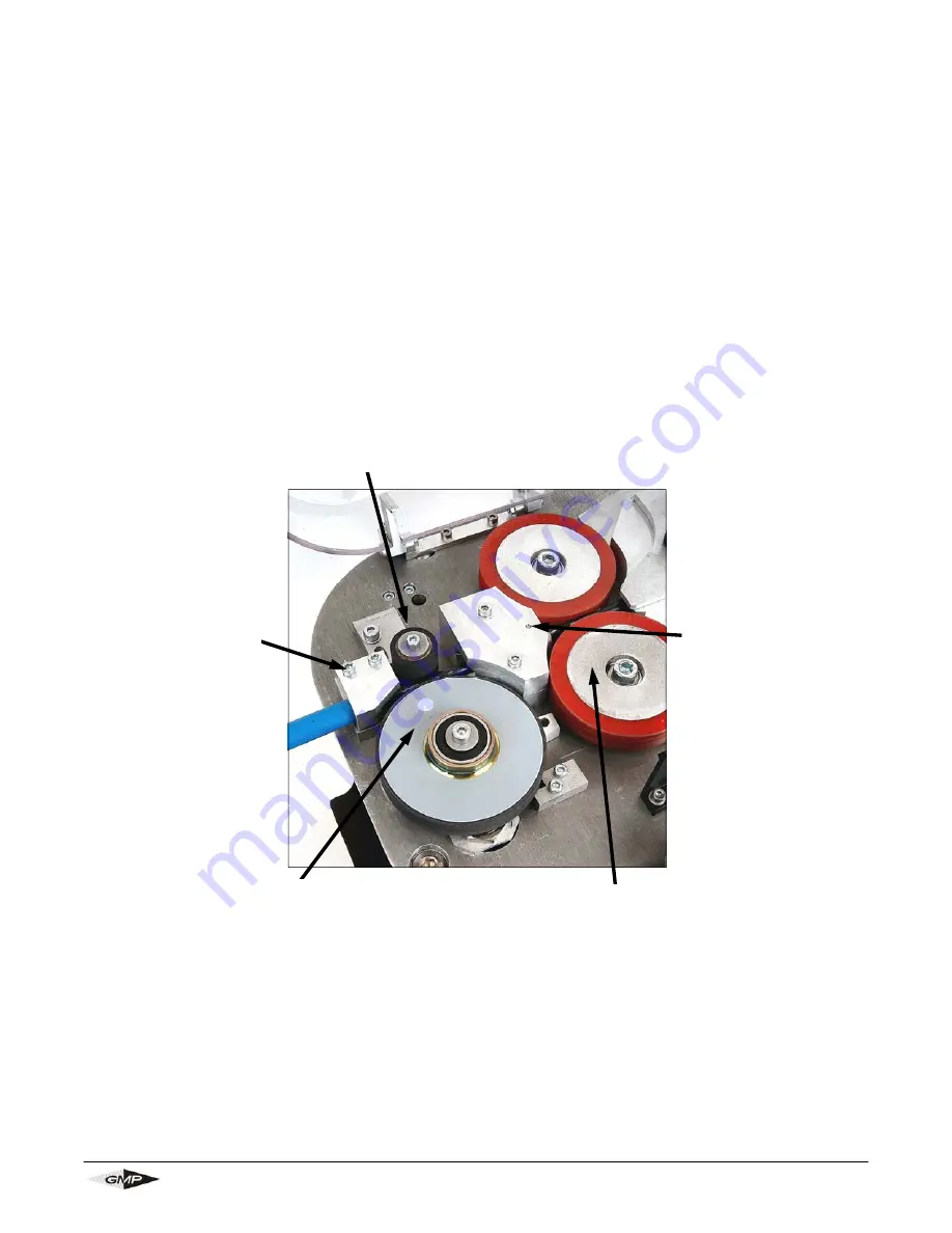
Infeed guide assy:
this should be kept
clean. Build up of dirt
etc on the faces will
cause the cable to
catch on the guide.
Clean with any work-
shop solvent. Pay
particular attention to
the joint faces of the
inserts and the hous-
ing.
Measuring system fixed roller:
this should be kept clean. Build up of dirt etc on the faces
will cause faulty readings of speed and/or distance. Clean with warm soapy water, wash off
and allow to dry. For stubborn marks and build up M.E.K* may be used.
Drive rollers:
these should be kept clean.
Build up of dirt etc on the faces will cause
slip and/or jerky feeding of the cable.
Clean with warm soapy water, wash off
and allow to dry. For stubborn marks and
build up M.E.K* may be used.
Measuring roller:
this should be kept clean.
Build up of dirt etc on the faces will cause
faulty readings of speed and/or distance.
Clean with warm soapy water, wash off and
allow to dry. For stubborn marks and build up
M.E.K* may be used.
In-feed Guide
Clamp:
this should
be kept clean. Build
up of dirt etc on the
faces will cause the
cable to catch on
the guide. Clean
with any workshop
solvent.
Summary of Contents for Breeze 89010
Page 31: ...Page 31 of 42 General Machine Products KT LLC Page intentionally left blank ...
Page 39: ...Page 39 of 42 General Machine Products KT LLC ...
Page 40: ...Page 40 of 42 General Machine Products KT LLC Page intentionally left blank ...
Page 41: ...Page 41 of 42 General Machine Products KT LLC ...


