


D1049
- SIL 3 Digital Output Driver NE Loads Bus Powered
G.M. International ISM0097-9
6
Functional Safety Manual and Application
Application of D1049S for NE load
Failure category
Failure rates (FIT)
λ
dd
= Total Dangerous Detected failures
0.00
λ
du
= Total Dangerous Undetected failures
1.90
λ
sd
= Total Safe Detected failures
0.00
λ
su
= Total Safe Undetected failures
170.63
λ
tot safe
= Total Failure Rate (Safety Function) =
λ
dd
+
λ
du
+
λ
sd
+
λ
su
172.53
MTBF (safety function, single channel) = (1 /
λ
tot safe
) + MTTR (8 hours)
661 years
λ
no effect
= “No effect” failures
271.27
λ
not part
= “Not Part” failures
31.60
λ
tot device
= Total Failure Rate (Device) =
λ
tot safe
+
λ
no effect
+
λ
not part
475.40
MTBF (device, single channel) = (1 /
λ
tot device
) + MTTR (8 hours)
240 years
λ
sd
λ
su
λ
dd
λ
du
SFF
0.0 FIT
170.63 FIT
0.00 FIT
1.90 FIT
98.90%
Failure rates table according to IEC 61508:2010 Ed.2 :
Failure rate table:
Safety Function and Failure behavior:
D1049S is considered to be operating in Low Demand mode, as a Type A module, having Hardware Fault Tolerance (HFT) = 0.
The failure behaviour of D1049S for NE loads is described by the following definitions:
□
Fail-Safe State: it is defined as the output being de-energized;
□
Fail Safe: failure mode that causes the module / (sub)system to go to the defined fail-safe state without a demand from the process;
□
Fail Dangerous: failure mode that does not respond to a demand from the process (i.e. being unable to go to the defined fail-safe state), so that the output remains energized
;
□
Fail “No Effect”: failure mode of a component that plays a part in implementing the safety function but that is neither a safe failure nor a dangerous failure.
When calculating the SFF, this failure mode is not taken into account.
□
Fail “Not part”: failure mode of a component that is not part of the safety function but part of the circuit diagram and is listed for completeness.
When calculating the SFF, this failure mode is not taken into account.
Failure rate data: taken from Siemens Standard SN29500.
Description:
The D1049S is a single channel digital output drivers, Bus powered for NE (Normally Energized) loads. The Safety PLC or DCS control signal enables the field devices through the
single channel digital output driver D1049S (1 intrinsic safety channel, Bus Powered), which provides the electrical isolation between Supply - Input and Output. The presence of the
input control signal is also indicated by a yellow LED on the front panel.
In order to interface the majority of field devices available on the market, two basic output circuits with different safety parameters (outputs A, B and C) are provided for channel.
The selection among the three output characteristics is obtained by connecting the field devices to a different couple of terminal blocks.
The field line and load fault detection is enabled, the override input is disabled and direct In / Out operation is selected, setting the internal DIP-switches in the following modes:
The module is powered by connecting 24 Vdc power supply to Pins 3 (+ positive) and 4 (- negative).
The Control signal from Safety PLC Outputs is applied to Pins 5 - 6.
The Output NE load is applied to Pins 13 - 16 or 14 - 16 or 15-16.
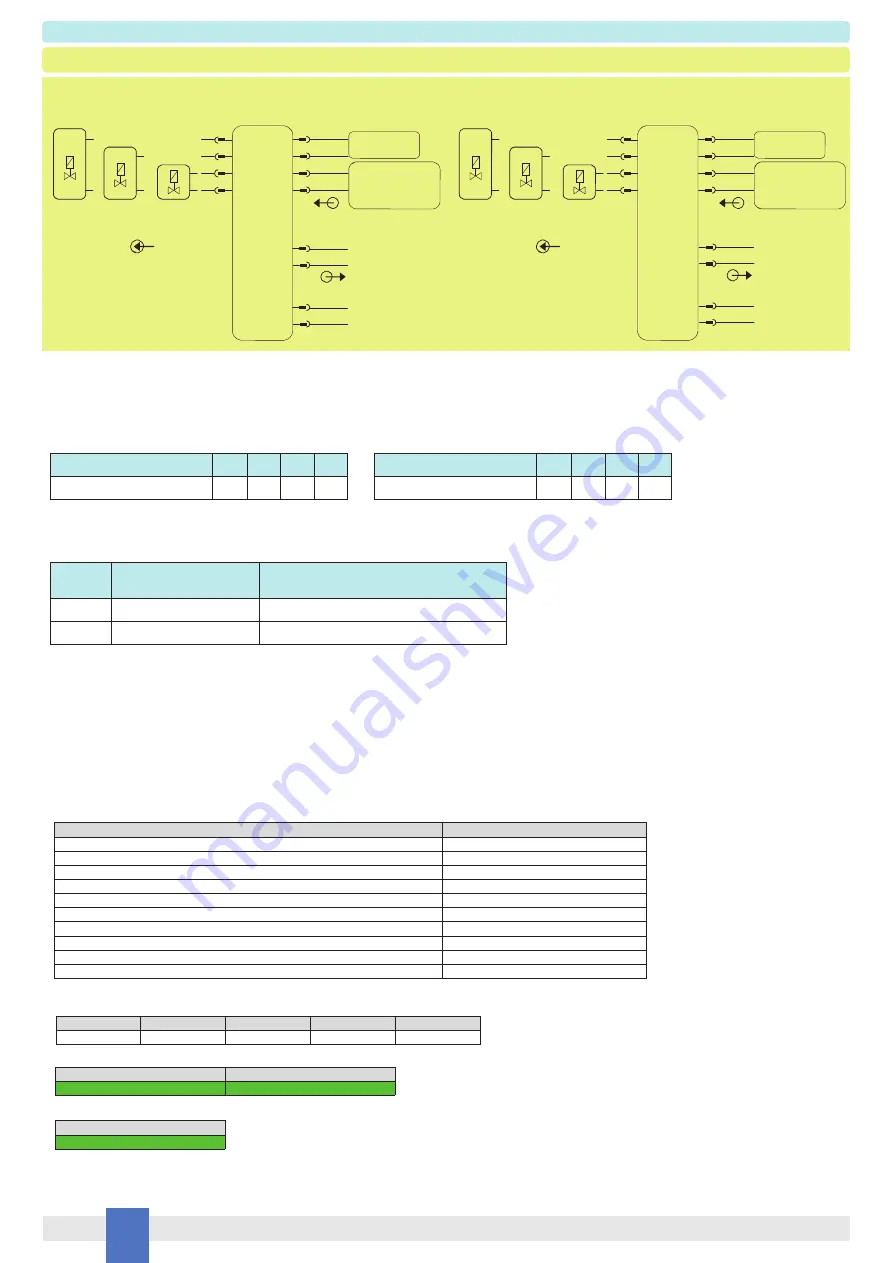
The following table describes the state (energized or de-energized) of the output when the Loop Control signal is in the High (20 to 30 Vdc) or Low (0 Vdc) state.
Operation
Input Signal State
Pins 5 - 6
Output State
Pins 13-16 (Out A) or 14-16 (Out B) or 15-16 (Out C)
Normal
High (20 to 30 Vdc)
Energized
Trip
Low (0 Vdc)
De-energized (as safe state condition)
De-energized to trip operation
D1049S
13
14
Out 1
15
+
Solenoid
Valve
16
-
+
Out C
Normal state operation
Output is de-energized
Out B
Out A
Solenoid
Valve
+
Solenoid
Valve
-
-
1 +
2 -
In 1
≥
20 Vdc
7 +
8 -
Must not be used
because disabled
Fault Output
Not used for
functional
safety purpose
D1049S
1 +
2 -
13
14
Out 1
15
+
Solenoid
Valve
16
-
+
Out C
In 1 = 0 Vdc
Output is energized
Out B
Out A
Solenoid
Valve
+
Solenoid
Valve
-
-
7 +
8 -
Fault Output
Not used for
functional
safety purpose
SW1 Dip-switch position
1
2
3
4
ON / OFF state
ON
-
-
-
SW2 Dip-switch position
1
2
3
4
ON / OFF state
ON
-
-
OFF
Must not be used
because disabled
3 +
4 -
Supply 24 Vdc
Control Signal from
Safety PLC Output
5 +
6 -
3 +
4 -
Supply 24 Vdc
Control Signal from
Safety PLC Output
5 +
6 -
T[Proof] = 1 year
T[Proof] = 12 years
PFDavg = 8.32 E-06
Valid for
SIL 3
PFDavg = 9.98 E-05
Valid for
SIL 3
PFDavg vs T[Proof] table
(assuming Proof Test coverage of 99%), with determination of SIL supposing module contributes >10% of total SIF dangerous failures:
PFDavg vs T[Proof] table
(assuming Proof Test coverage of 99%), with determination of SIL supposing module contributes
≤
10% of total SIF dangerous failures:
T[Proof] = 20 years
PFDavg = 1.66 E-04
Valid for
SIL 3
Systematic capability SIL 3


